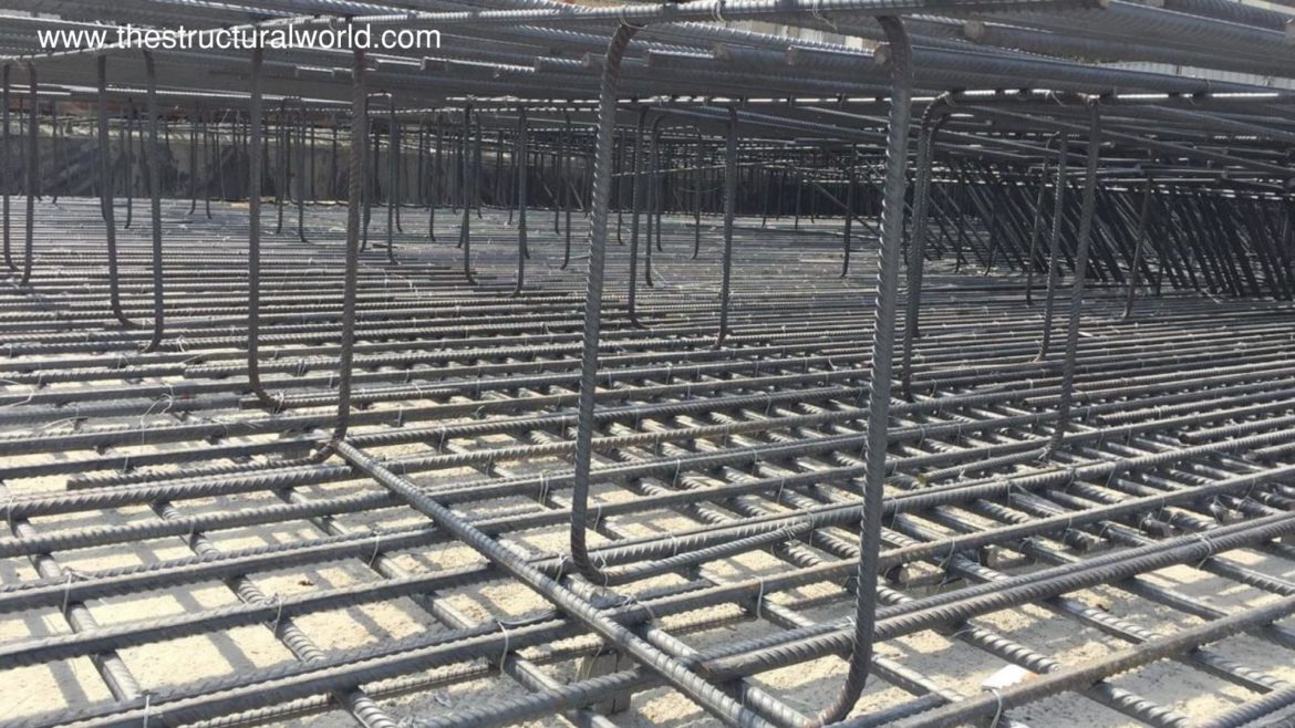
During site construction, Reinforcement Chair or sometimes called as Rebar Spacer, Steel Chair or simply Chair is commonly seen in raft or mat foundations. This is commonly shaped as Z or inverted U type reinforcement to evenly separate the top and bottom mesh reinforcement or to provide enough space between the meshes. In the installation of the main mesh reinforcement during construction, steel chairs play a vital role to keep the spacing evenly and hold the mesh reinforcement in place before and after concreting. That is why Steel chairs should be designed also accordingly and not taken for granted.
This article will show you how to design reinforcement chairs. And Reinforcement chair design can be further understood by showing an illustrative example given in the image below. Let us design the reinforcement chairs needed as per the typical raft details that are given below:
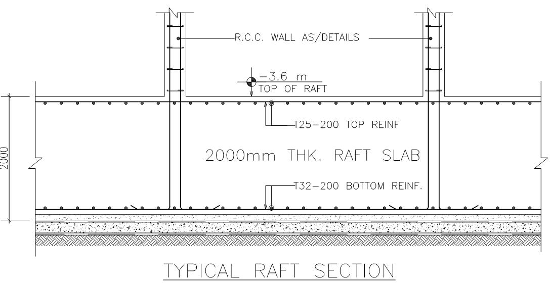
Summarizing the image above, the following are given:
- Raft thickness: 2000mm
- Main Mesh Reinforcement:
- Bottom: T32-200mm both ways
- Top: T25-200mm both ways
Solution:
Load Calculations.
The first thing to consider is how much the weight of the rebar reinforcement in the raft which is tabulated as:
- T25: 0.0378 kN/m length
- T32: 0.0632 kN/m length
An additional 1.5kN/m2 Live Load to be considered to account for any construction loads.
If you are wondering rebar weight with a unit of kN/m is derived using the formula:
where: D=diameter
Calculate for Weight of Rebar that the rebar chair will carry:
- Top Reinforcement: (0.0378 kN/m/0.20) x 2 layers = 0.378kN/m2
- Bottom Reinforcement: (0.0632 kN/m/0.20) x 2 layers = 0.632kN/m2
Assumed Diameter of Reinforcement Chair to use:
Let us use say T25 for chair reinforcement
Check Buckling Capacity of T25 Rebar using the Euler’s Formula:
Maximum Buckling Force is given by:
where:
- Pcr: allowable buckling force
- E: Modulus of Elasticity of Rebar can be taken as 200, 000 MPa or 200×106 kPa
- I: Rebar’s area moment of inertia in m4 with the formula:
and I is equal to 1.917 x10⁻⁸ m4
- K: effective length factor = 1.0
- L: unsupported length= 2.0m
Substituting to the above equation:
- Pcr = 9.46kN
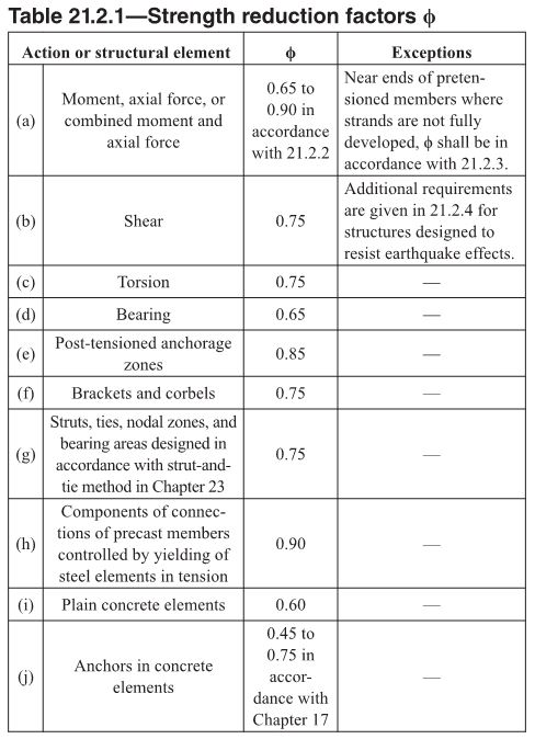
Pcr = 0.75×9.46kN= 7.1kN
where:
Solving for the Number of Reinforcement Chair required per square meter:
Since the chair reinforcements support only the top layer, then we will consider the weight of top mesh reinforcement as dead load.
No of Bars/m2 = Factored Load /
where:
Factored Load = 1.2Dead Load + 1.6 Live Load
= 1.2 x 0.378kN/m2 + 1.6 x 1.5kN/m2
= 2.85 kN/m2
No of Bars/m2 = 2.85 kN/m2/7.1kN= 0.40 bar/ m2 ;
Hence, the reinforcement chair required is 1 T25 reinforcement chair per square meter.
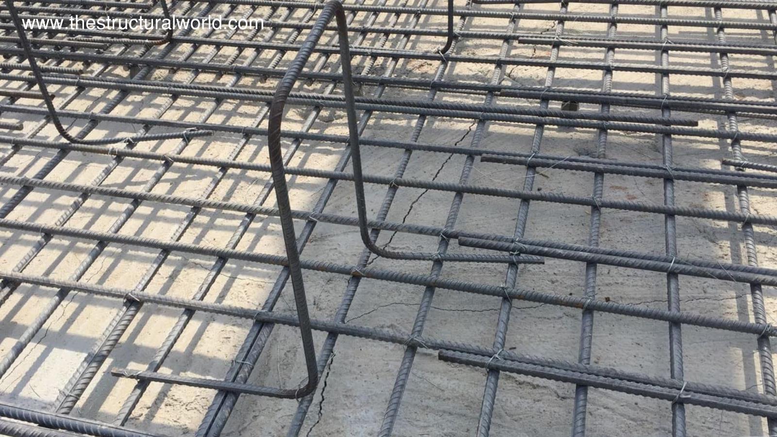
An Image view of Reinforcement Chair
Since the reinforcement chair supports only the top mesh reinforcement, the bottom mesh reinforcement needs as well as support to maintain its concrete cover. Likewise, a spacer is required. There are so many types of spacers that can be used during site construction, but the most commonly used at the site is the concrete spacer. But how do we check if the dimension of the concrete spacer is enough so it can withstand the load of the raft reinforcement it carries? That will be tackled in the next article-“Design of Concrete Spacer” so stay tuned or subscribe to our newsletter for any updates and notification.
What do you think of the above this article? Tell us your thoughts! Leave your message in the comment section below. Feel free to share this article, subscribe to our newsletter and follow us on our social media pages.
[DISPLAY_ACURAX_ICONS]


“The reinforcement chair required says 3 bars per square meter” seems to be incorrect. Since the buckling force is 7.1 kN for each 25 mm dia chair bar, then no. of bars required per meter should be calculated total load i.e. (1.6×1.5+1.2×0.378). Please clarify.
Hi Ashok! Based on the above example, that means 1 no. of T25 reinforcement chairs should be used in every 1.0m x1.0 m of the raft foundation as per the corrected calculations.
HI
Surely there is an error in the last step ,because if we depend on the last step that’s means as we increase the steel bar diameter of the chair we will need more chairs and that is not logical. Please Recheck .
Regards
Hi El-Master, thanks for pointing out. The result of the calculations has been corrected and is now updated. Cheers!
Just reverse the last formula. It must be (1.6*construction live load +1.2*top steel weight)KN/m2/(0.75*Pcr)KN
One chair has two legs, so the chair capacity is 7.1×2=14.2 KN
It means that one chair can carry 14.2 / 2.85 = 5 m2
Any objection to this comment? Or it is deemed true. We should have the minimum and maximum results.
The loads from which the steel chair carries came from the top mesh which is a vertical load. This will be resisted by one leg only, which is the horizontal bar or the upper part of the inverted U that is why the calculation considers 1 leg only.
I don’t get it.
If the top mesh is supported in the middle of “U part” of the chair it means that first leg takes 1/2 of the vertical force and second leg also takes 1/2. (Legs are vertical elements in this case)
It’s impossible to support top mesh in axis of buckled bar because of bending diameter(according to EC bending diameter equals to 7 diameters of bar for #25, 7×25=175mm, and 175mm/2=87,5mm for 90degree angle).
Assuming, the nearest point to buckled axis where force can be applied is 87,5+25/2 = 90mm. It means you have to include both legs of the chair.
Any objections?
You are wrong comparing horizontal bar (head) which is bent, and two vertical legs which are compressed with buckling.
You can check capacity of head chair but not using above desing.
Where did you get 1.5kpa construction live load? Is there a code specifying this?
Obviously, construction live load should be considered as during the installation of raft reinforcement, there are movements/activities going on above it. You can refer to ASCE-7 for the different live loads.
What is the IS code clause number for calculating factored load combination?