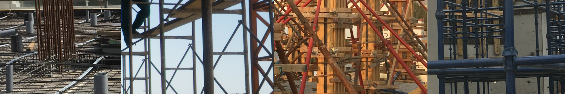
Our previous article tackled the overall view on how the Structural Assessment of existing buildings and Integrity check should be done. One of the procedures in the investigation of the building integrity is to gather the actual concrete or material properties and data in order for us to dig into further investigation. This task cannot be made possible without the laboratory test and procedures on the concrete samples taken from the site. A non-destructive test is recommended in conducting the mentioned investigation. Check out the below methods of Non-destructive testing and procedures required in order to check the actual strength of concrete structures.
1. Concrete Coring
A number of cores should be considered and should be taken in different locations approved by the assigned Engineer. During the coring process, care should be taken into consideration to avoid further damage to the existing structures. To avoid cutting of steel rebar, a concrete rebar detector should be used to locate the existing rebar prior to drilling. The rotary core cutting machine with hollow diamond bits cooled with fresh water should be used in drilling. The obtained core samples should be clearly marked and protected to avoid damage. These samples will be transferred from the site to testing laboratories for physical and mechanical examination to determine the actual densities and compressive strengths of each sample.
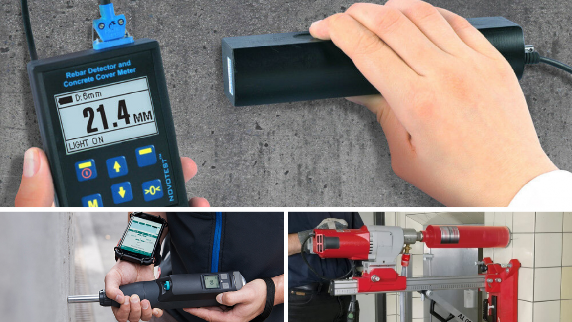
Concrete Rebar Detector

Rotary Core Cutting Machine
2. Rebound Hammer Test
Also known as the Schmidt hammer, this test can verify the uniformity of concrete as well as its compressive strength. This device can be used exclusively on the surface of the concrete being tested. The device measures the rebound value R. There is a specific relationship between this value and the hardness and strength of the concrete. Each test surface should be tested with at least 8 to 10 impacts. The individual impact points must be spaced at least 20 mm apart. After every impact, the rebound value R is displayed by the pointer on the scale of the device. The rebound value R is automatically registered on the recording paper. The step-by-step procedure, its do’s and dont’s on how is it being used is available on its manual when you purchase this product.

Schimidt Hammer Test
3. Concrete Cover Investigations
The inspector should conduct the concrete cover survey at selected areas in the concrete structures in considerations. This is to indicate the depth of reinforcement. A low concrete cover should be identified and recorded to make sure if additional cover is needed. The thickness of the concrete cover can be measured using an electromagnetic cover meter.
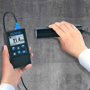
Electromagnetic Concrete Cover Meter
4. Measurement of Carbonation
Carbonation is one of the reasons for the corrosion of steel reinforcements. The concrete cover should be checked on-site to make sure that it is sufficient enough so that the carbonation should not reach the steel reinforcement throughout the life of the structure. It is important for engineers to measure the depth of carbonation to determine the rate and cause of corrosion.
The depth of carbonation can be measured on a freshly exposed surface of the concrete by chipping the drilled hole used in concrete sampling. This can be tested by applying a chemical indicator. The difference in alkalinity between the carbonated and un-carbonated concrete can be seen if the color changes. The indicator to be used is a solution of 1% phenolphthalein in diluted ethyl alcohol which changes each color from transparent to purple-pink as the PH value of above 10 rises. Consequently, the outer carbonated layer of concrete retains its natural color while the un-carbonated stained pink. This test can be applied only on freshly exposed surfaces free from dust.
|
Tested Member |
Locations | Carbonation (mm) | Ave. Actual Concrete Cover(mm) |
|
1st Floor Columns |
1 |
20 | 30 |
| 2nd Floor Beams | 2 | 15 | 25 |
| Typical Floor Columns | 3 | 10 |
35 |
Table 4.0: Sample Carbonation Results
Referring to Table 4.0 above, the maximum depth of carbonation for column and beam is 20 mm and 15 mm respectively. These are less than the average concrete cover in tested structural members. Therefore, the reinforcement is protected and no corrosion presence is caused by carbonation.
5. Concrete Dust Samples
Dust samples are also considered in the structural assessment of the existing building. These samples should be taken to determine the chloride contents of the concrete. This can be determined using the Sherwood Model 926 Chloride Analyzer. The results are usually expressed as the chloride iron content (CI) by weight of the concrete samples including the aggregate. These can be converted to the chloride ion by weight of cement after determination and knowing the cement content. The CI by weight is useful to enable comparisons against the recommended level in accordance with the code of practice.
The concentration of the chloride, alkalinity, and the type of cement used can contribute to the chloride content in concrete. It is critical to the life of the steel reinforcement as it may rust as a result. However, the maximum chloride content should be tolerable according to the standard set by code specifications mentioned in CIRIA 2002. The actual chloride content of each dust sample was determined according to the code set forth in BS1881: Part 124: 1988.
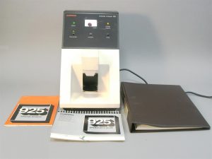
Chloride Analyzer
6. Ultrasonic Pulse Velocity
The ultrasonic pulse velocity tests are used to verify the quality of concrete. Concrete with pulse velocity greater than 4000 m/s is considered to be of good quality. The ultrasonic pulse velocity test can perform when a pulse of longitudinal vibrations is produced by an electro-acoustical transducer held in contact with one surface of the concrete under test. After traversing a known path length in the concrete, the pulse of vibrations is converted into an electrical signal by a second transducer and electronic timing circuits enable the transit time of pulse to be measured. The velocity criterion for the quality grade of concrete can be checked using a direct and in-direct transmission according to the tables below taken from BS EN 12504-4-2004. The recorded ultrasonic pulse velocity in each core sample is then be classified accordingly.
|
No. |
Pulse Velocity in Core Probing |
Concrete Quality Grading |
|
1 |
Above 4500 |
Excellent |
|
2 |
3500 to 4500 |
Good |
|
3 |
3000 to 3500 |
Medium |
|
4 |
2000 to 3000 |
Poor |
|
5 |
Less than 2000 |
Very Poor |
Table 6.1 Velocity Criterion for Concrete Quality Grading ( Direct)
|
No. |
Pulse Velocity in Core Probing |
Concrete Quality Grading |
|
1 |
Above 4000 |
Excellent |
|
2 |
3000 to 4000 |
Good |
|
3 |
2500 to 3000 |
Medium |
|
4 |
1500 to 2500 |
Poor |
|
5 |
Less than 1500 |
Very Poor |
Table 6.2 Velocity Criterion for Concrete Quality Grading ( In-Direct)
7. Electrical Resistivity Measurements of Concrete Surface
The surface resistivity measurement provides useful information about the state of concrete quality. By evaluating the electrical resistance of concrete, it is possible to assess the probability of reinforcement corrosion. Because the corrosion of steel reinforcement in concrete is an electro-chemical process that creates a current flow causing the metal to dissolve. Electric current is passed through the outer probes and the potential drop is measured by the inner probes. From the current and voltage drop, the resistivity of concrete can be measured. The concrete resistivity meter replaced the Rapid Chloride Permeability Test and surface resistivity for ASTM C1202 and AASHTO T277. The Surface Resistivity test is a much quicker and easier test for estimating concrete permeability. It is a proven method that can replace the more laborious rapid chloride permeability test.
8. Electro Half Cell Potential Measurement Test
Since corrosion is an electro-mechanical process, it is possible to obtain an indication of whether the steel reinforcement in concrete is in the corroded stage. The state of steel reinforcement can be verified by measuring electrical potentials by means of the Electro Half Cell Potential Measurement Test. One terminal of high impedance milli-volt meter can be connected to a point on the reinforcement and the other terminal to a half-cell or copper sulfate or silver chloride which placed in contact with the concrete surface. The half cell usually consists of a copper electrode immersed in an electrotype of copper sulfate solution. Corrosion is likely to be negligible in readings less than -200 mV.
References: ACI 318-11, ACI 417R 1991, ASTM D512-89 1999, BS6089, 1981, BS5328 PART 1, BS1377 PART 3 1990, CIRIA REPORT 2002.
What do you think about this article? We love to hear your thoughts! Leave a message in a comment form below. You can also follow, like, and subscribe to our social media pages below to be updated with the latest posts.
[DISPLAY_ACURAX_ICONS]