In our previous article Construction Joints in Slab we tackled about how, when and where we are considering a construction joint in slabs. We have learned that terminating a slab casting has a shear friction check to consider before casting another fresh concrete. Because originally slabs were designed as a continuous slab which means that the reinforcements are fully continuous, but since we are casting the slab at different times, we are terminating the continuity of the other thus the output results in stresses is different already compared when it is a continuous one. In this aspect we need to check for any reinforcement needed in between the construction joint to resist the shear transfer across the slab plane and any potential cracks that may occur.
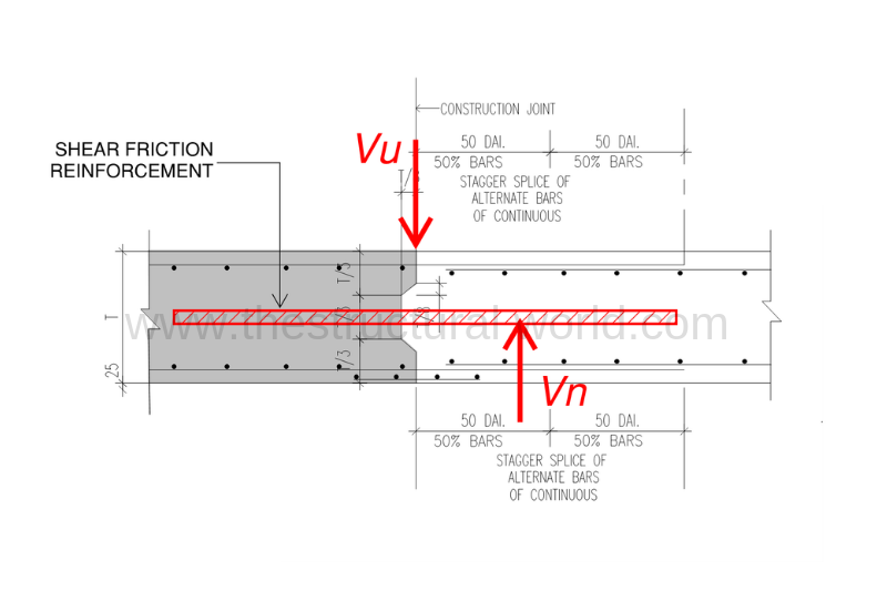
The shear friction concept assumed that such a crack is formed when concrete will be cast at different times and that reinforcement is provided across the crack to resist relative displacement along it. The reinforcement in tension provides a clamping force, Avf x fy across the crack faces.
How to Perform a Shear Friction Check?
To recap, shear friction check can be performed using the following equation set forth by the code:
According to ACI 318-14, Shear friction check shall be performed to address the possible failure by shear sliding on a plane and design shear strength across the assumed shear plane shall satisfy:
ΦVn ≥ Vu [Section 22.9.3.1]
where:
- Φ=0.75 for shear
- Vn: Nominal Shear (shear due to applied reinforcements)
- Vu: Maximum Shear (maximum shear due to factored loadings)
If shear-friction reinforcement is perpendicular to the shear plane, nominal shear strength across the assumed shear plane shall be calculated by:
Vn = µ x Avf x fy [Section 22.9.4.2]
where:
- Avf : area of reinforcement crossing the assumed shear plane to resist shear (e.g. mesh reinforcement in case of slab)
- µ: coefficient of friction according to table 22.9.4.2. of ACI 318-14. Refer to previous article.
Worked Example:
In an approved first floor framing plan shown in the figure below, we have a slab ready for casting, since the slab is too wide in dimensions, a series of concrete casting was proposed by the contractor and it will be cast in two different phases. The shaded slab will be cast first and the remainder will be poured after some time. It is required to check or design if any additional reinforcement is needed as shear bar according to slab pouring termination. Use steel reinforcement yield stress, fy=460Mpa.
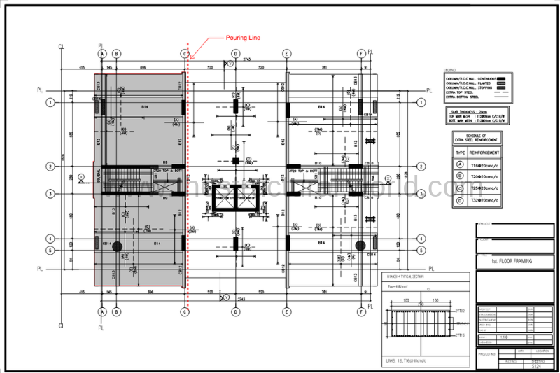
Solution:
Based on the above drawing, the given mesh is T12@200mm c/c Top and Bottom, Both ways. We will consider the tension reinforcement and conservatively assumed that the shear force will be resisted by the bottom mesh.
Solving for the area of Mesh Reinforcement, Avf:
Avf= (113/0.2) = 565mm2/m x 1m = 565mm2
Vn = µ x Avf x fy
= [1.0 x 565mm2 x 460 N/mm2][1/1000]
Vn = 260 kN
ΦVn = 0.75(260kN)
ΦVn = 195 kN
The maximum shear, Vu shall be taken from the factored loadings. In this example, the slab has been designed by the SAFE program. It is more convenient for the designer to use the existing SAFE model to get the maximum shear, Vu. To be noted that Vu can also be taken at any means or through manual calculations depending on the designer’s prerogative. For the purpose of presentation, we will get the maximum shear force, Vu through the shear force diagram of the SAFE model of the shaded slab above and the figure below are the shear force diagram results.
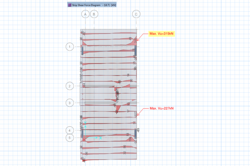
From Shear force diagram taken from SAFE result above; Vu=315kN, since ΦVn < Vu, then additional shear reinforcement is required!
To satisfy the equation ΦVn ≥ Vu of ACI 318-14, Section 22.9.3.1, additional rebar is needed on the areas having the maximum shear. Let us say that we are adding an additional reinforcement T10@200mm c/c, then the mesh reinforcement, Avf will be:
Avf= (113/0.2) = 565mm2/m x 1m = 565mm2
Additional Avf= (79/0.2) = 395mm2/m x 1m = 395mm2
Total Avf= 960 mm2
Vn = µ x Avf x fy
= [1.0 x 960mm2 x 460 N/mm2][1/1000]
Vn = 441.6 kN
ΦVn = 0.75(441.6kN)
ΦVn = 332 Kn > Vu=315kN, Hence OK!
Therefore an additional T10@200mm c/c should be added on the portion having the maximum shear as per the SAFE shear diagram results.
Drawing Details
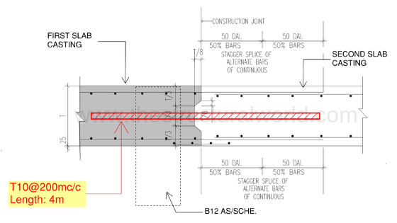
As a designer, you should also be able to interpret the above calculation results in the drawing for the site engineer to be implemented prior to concrete casting. Refer to the figure below for the recommended details:
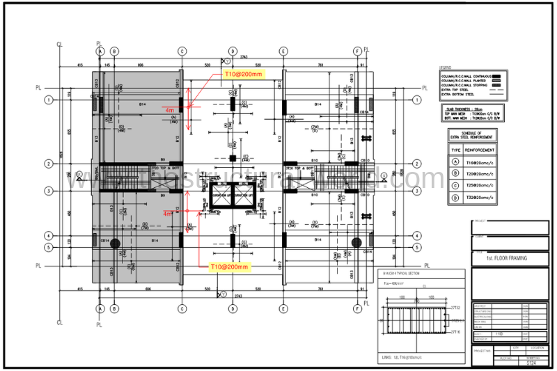
It is noticed on the above figure that an additional steel reinforcement of T10@200mm c/c has been added on the areas of the slab that the maximum Vu exceeds ΦVn. The rests along the pouring line don’t need additional bars since it satisfies the code requirement.
Slab Section along the Pour Line
Constructability
- Construction joint shall be cleaned and laitance removed before new concrete is placed.
- The surface of the first pour should be intentionally roughened to increase the bond strength and to provide an aggregate interlock.
What do you think of the above article? Tell us your thoughts! Leave your message in the comment section below. Feel free to share this article, subscribe to our newsletter and follow us on our social media pages.
[DISPLAY_ACURAX_ICONS]


Interesting sharing! What about check for large slab pour, for example to a 4m thick piled raft, where construction joint is horizontal in plane? I imagine the shear friction this time is resisted by concrete section only. Any example on that?
Interested to know??
hi. Based on your sentence, “We will consider the tension reinforcement and conservatively assumed that the shear force will be resisted by the bottom mesh.”, does it mean that we actually should use the tension reinforcement of beam or slab as Avf in the calculation?
No Shean, We just used the tension bar for Avf consideration conservatively for additional safety considerations. But you can also consider the addition of compression reinforcement in the Avf calculations. It’s your call as a designer!
As per ACI 318, If a moment acts across the shear plane, the shear friction reinforcement should be placed primarily in the flexural tension zone. Accordingly, the top flexural reinforcement should be utilized for shear friction and if additional shear friction reinforcement is required should also be placed in flexural tension zone.
Why would not we take the maximum capacity of shear strength of concrete only without any participation of bottom and top mesh ?
Concrete shear resistance which is provided by aggregate interlock may not be very reliable at a construction joint (shear plane) since number of aggregate at the construction joint is less than that in the middle of the member per say. That’s why is critical to design reinforcement across the construction joint that would resist shear transfer between two concrete beams/slabs cast at different time intervals. That’s my understanding, I could be wrong though.
Thank you sir
but shear friction cause tension in bars so I think that we can not use existing reinforcement as a shear friction reinforcement because this reinforcement was designed to resist bending moment and shear friction will cause additional tension due to clamping force at construction joint
My thoughts are same as yours…why ACI not clarified this confusing topic even in 2025 edition?
THIS CALCULATION IS FOR FLAT SLAB OR BEAM SLAB ? AND WHY YOU HAVE NOT TAKEN CONSTRUCTIN JOINT AT L/3 FROM SUPPORT?
It’s applicable flat or solid slabs. Yes, L/3 it is. Please read the related article Construction Joint in Slabs
This steel need to be separate in addition to bending to be place ideallly at the mid of shear stress diagram
Can you tell me how you have calculated Avf where is 113 and 0.2 coming from?
As per ACI 318 chapter22,clause 22.9.5 ( Commentary)
If a moment acts across the the shear plane, the shear friction reinforcement should be placed primarily in the flexural tension zone. Accordingly, the tension reinforcement could be utilized for shear friction and if required additional shear friction reinforcement shall be also added in the tension zone