Boundary Zones or Boundary Elements
Another category in a shear wall or wall design is to determine the area of boundary zones or boundary element. Boundary Zones which is also known as Boundary Element is a portion along wall and diaphragm edge, including edges of openings, strengthened by longitudinal and transverse reinforcement. It is a region or a zone in a wall wherein a confinement reinforcement is needed. In layman’s term boundary zones in walls are with reinforcements that are usually larger in diameter that can be found in corners, near the corners, intersections and or at the end of the wall. For the boundary zones to be strengthened, a greater number of rebar are to be provided with the same thickness as the rests of the wall. But in some cases, the boundary zones or boundary element can also be enlarged. These areas should be enclosed by ties satisfying our design codes.
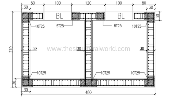
Although the code does not require concentrated reinforcement at these zones, it is a good practice to at least use larger bars. The most common boundary zones that we can encounter in the design are on core walls or lift shaft as shown on the Figure-A below showing confined areas of the wall. This is done to resist stress reversal and prevent reinforcement buckling near the edges.
How to determine the Boundary Zones or Boundary Elements?
Having said the above description, how do we consider these confined regions? To determine the boundary zone, the structural design codes such as UBC 97, IBC and ACI set standards in considering as such. For the sake of discussion, we will consider the ACI 318-14 approach in the determination of the boundary zones or elements as this code has a simpler and easy to understand method. Not all the walls need to be confined with larger rebar, a quick check is needed to identify these zones accordingly. Of course, if the wall in considerations does not meet such requirements, confinement zones are not required.
Boundary Zone / Boundary Element Check as per Section 18.10.6.2
According to ACI 318-14 Codes Sections 18.10.6.2, the need for special confinement reinforcement in boundary elements applies to the walls or piers that are effectively continuous from the base of the structure to the top of the wall and are designed to have a single critical section for flexure and axial loads. Boundary elements are required if:
where:
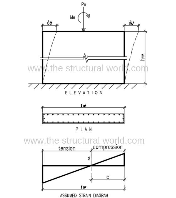
c: depth from the neutral axis to the extreme compression fiber
lw : horizontal length of the entire wall or of a segment of wall considered in the direction of shear force
hw : height of the entire wall, or segment of the wall considered
δu : design displacement, defined as the total lateral displacement deflection of the top of the building for the design-basis earthquake.
δu /hw > 0.005
To further understand the above equation, take a look at the wall diagram below:
Boundary Zone / Boundary Element Satisfying Section 18.10.6.2 Check
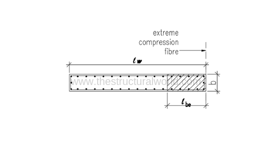
If the wall in consideration satisfies the above requirement (Eq. 18.10.6.2) then, the length of the boundary zone or element, lbe shall extend horizontally from the extreme compression fiber to at least the greater of c – 0.1 lw and c/2. The width b, shall be at least equivalent to hu/16.
The Boundary Zone / Boundary Element Traverse Reinforcement
- Traverse reinforcement shall comprise either single or overlapping spirals, circular hoops, or rectilinear hoops with or without crossties.
- Bends of rectilinear hoops and crossties shall engage peripheral longitudinal reinforcing bars.
- Crossties of the same or smaller bar size as the hoops shall be permitted, subject to the code limitation.
- Where rectilinear hoops or crossties are used, they shall provide lateral support to longitudinal reinforcement.
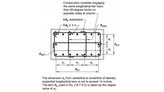
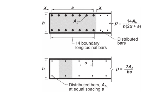
Reinforcement shall be arranged such that the spacing hx of longitudinal bars laterally supported by the corner of a crosstie or hoop leg shall not exceed 14 inches around the perimeter of the column.
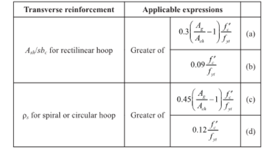
Design of Traverse Reinforcement for Boundary Zone / Boundary Element
The amount of traverse reinforcement shall be in accordance with Table 10.10.6.4 (f) below.
The requirement that the horizontal web reinforcement is anchored within the confined core of the boundary element and extended to within 6 inches from the end of the wall applies to all horizontal bars whether straight, hooked or headed, as shown in Figure R18.10.6.4.1.
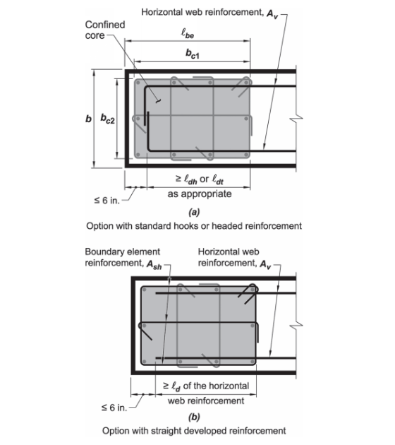
Figure R18.10.6.4.1 of ACI 318-14 : Development of Wall Horizontal Reinforcement in Confined Boundary Element
Summary:
Figure R18.10.6.4.2 summarizes the boundary element requirements for walls, as shown on the figure below:
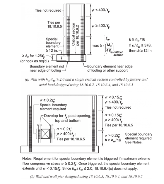
For walls that do not require boundary element, cyclic load reversal may still lead to buckling of steel reinforcements near the edges of the wall. The code suggests typical reinforcement ratios as indicated in Figure R18.10.6.5. Nevertheless, ties are still necessary to inhibit buckling. The addition of hooks or U-stirrups at the ends of horizontal wall reinforcement provide anchorage so that the reinforcements will be effective in resisting shear forces as well as to inhibit buckling of vertical reinforcement near the edges. For walls with low in-plane shear, the development of horizontal reinforcement is not necessary.
References:
Reinforced Concrete Mechanics and Design by James K Wight and James MacGregor
Building Code Requirements for Structural Concrete ( ACI 318-14) and Commentary (ACI 318R-14)
Uniform Building Code 1997 Volume 2
What do you think of the above this article? Tell us your thoughts! Leave your message in the comment section below. Feel free to share this article, subscribe to our newsletter and follow us on our social media pages.
[DISPLAY_ACURAX_ICONS]