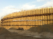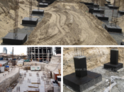
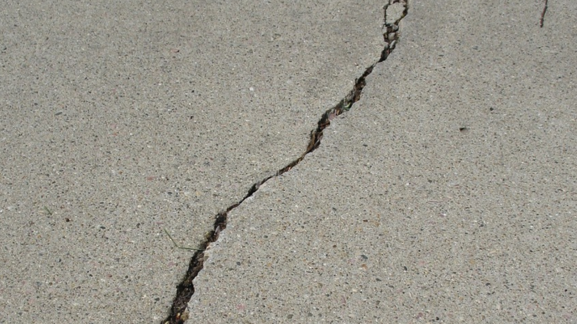
When the foundation of our building is technically lower compared to the groundwater table following a soil laboratory test results, then the ground water might find it way through the bottom or top of our foundation to start affecting our rebars. We all know that a steel reinforcement is prone to corrosion when exposed to water which may affect the strength of our rebar. A rusty rebar means deterioration in the stability of our foundation, because it reduces the structural durability and capacity. Aside to the fact that cracks are aesthetically unaceptable, it may lead also to the loss of the serviceability of the structures like the leakage of water or damage to finishes. In this regards as a structural engineer, a crackwidth check should be included in the design.
Crackwidth check should perform on our foundation or retaining structures exposed to water to make sure that the reinforcement with the help of concrete cover we provided is enough already to neutralize the water seepage, otherwise an additional rebar is a must. Crack widths shall be control in accordance to the referenced code and standard ACI 224R.
The maximum Allowable Crack Widths according to ACI 224R-01 is shown on the table below:
Exposure Condition | Crack Width (mm) |
|---|---|
| Dry air or protective member | 0.41 |
| Humidity, moist air, soil | 0.31 |
| Deicing chemicals | 0.18 |
| Seawater and seawater spray, wetting and drying | 0.15 |
| Water-retaining structures | 0.10 |
The above values can be superceeded by the requirement set by your local authority in jurisdiction.
How to Perform Crack Width Check
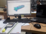
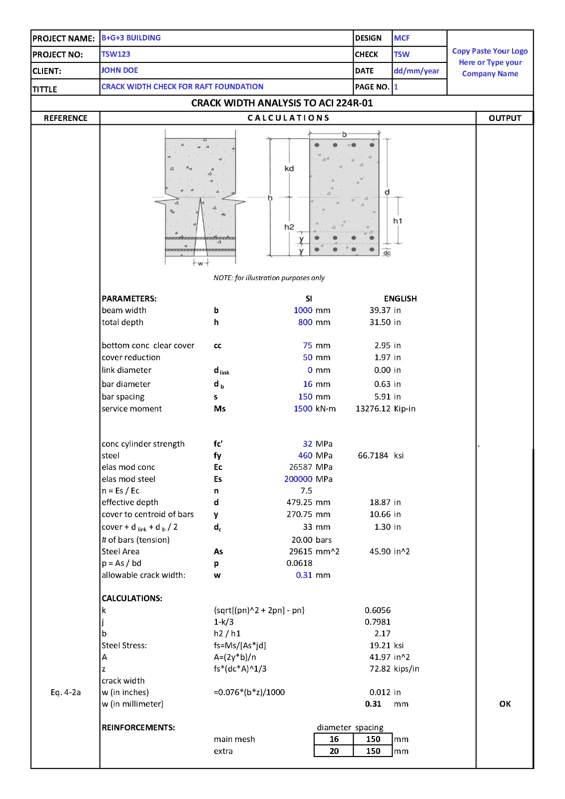
Designing the crackwidth requires the design moment under service load or service envelope. This can be done by modeling the raft foundation using CSI SAFE program. The design moment can be extracted by designing the raft foundation first. To design the raft foundation, refer to our previous article for further reference and guidance.
The requirements for flexural control in slabs/raft foundations are based on statistical analysis of maximum crack width data from a number of sources. The equations that were considered to best predict the probable maximum bottom and side crack width is as per the equation 4-2a of ACI 224R-01.
ω = 0.076ßfs³ √dcA x 10-³
where:
- ω = most probable crack width, in.
- β = ratio of distance between neutral axis and tension face to distance between neutral axis and reinforcing steel
- fs = reinforcing steel stress, ksi.
- dc = thickness of cover from the extreme tension fiber to the closest bar, in.
- A = area of concrete symmetric with reinforcing steel devided by number of bars, in.²
Our team developed a user friendly spreadsheet to help us analyze/check the crack width considering the above equations. Grab your copy here!
What do you think about this article? Tell us your thoughts! Leave a comment on the section below. Subscribe to our newsletter to be updated with the latest posts or follow us on our social media pages on the below icons.