
A seismic analysis in the design of buildings especially high rise towers is a very important factor to consider. Because earthquake loads together with the wind loads considerations have a huge impact on the design result. In fact, most of the building design result is governs with the seismic loads. But what does the code says about the design of building in terms of earthquake load consideration?
In this article, we will learn the Seismic Analysis provisions as specified in the Uniform Building Code-97 (UBC-97). We will summarize the different seismic parameters that we often use in the Seismic Analysis. These parameters are specified below; most of the images here are an excerpt from the UBC-97 code.
Determination of Linear Static Seismic Lateral Force using UBC-97 Code:
1. Design Base Shear (V):
Base Shear (V) is the total design lateral force or shear at the base of the structure. The design base shear in a given direction is specified by the formula:
![]()
where:
T: Fundamental Period of the structure in the direction under consideration.
I: Seismic importance factor.
Cv: Numerical coefficient depends on the soil conditions at the site and the seismicity of the region.
W: Seismic Dead Load
R: Factor which accounts for the ductility and over-strength of the structural system
The design base shear is depending on the seismic zone factor (Z). The base shear specified previously is subjected to three limits:
- The total design base shear need not exceed:
![]()
and shall not be less than:
![]()
where:
Ca: Another seismic coefficient depending on the soil conditions at the site and regional seismicity.
In the highest zone seismicity (Zone – 4) the base shear must be greater than:
![]()
where:
Nv: Near – source factor that depends on the proximity to an activity of known faults near the structure.
2. Seismic Zone Factor (Z):
There are five seismic zones consideration and defined in table 16-I of UBC-97 code. The numerical values of Z are:
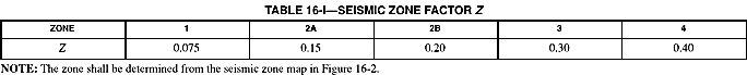
The value of the coefficient thus normalized can be viewed as the peak ground acceleration (Z), in percent of gravity, in each zone.
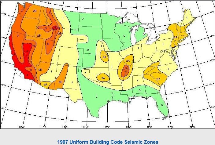
The zone for a particular site is determined from a seismic zone map (for the United States see the figure below).
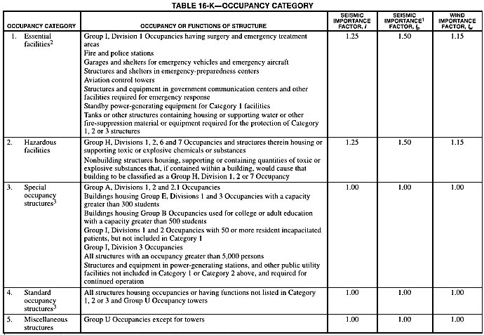
3. Seismic Importance Factor (I)
The importance factor (I) is used to increase the margin of safety for essential and hazardous facilities. For such structures I=1.25.
- Essential structures are those that must remain operative immediately following an earthquake such as emergency treatment areas and fire stations.
- Hazardous facilities include those housing toxic or explosive substances.
Below are the excerpts of Table 16-K from UBC-97
4. Structure Period (T):
The building period may be determined by analysis or using the empirical formulas. A single empirical formula may be used for all framing systems:
![]()
Where:
Ct= 0.035 (0.0853) for steel moment-resisting frames.
Ct= 0.030 (0.0731) for reinforce concrete moment-resisting frames.
Ct= 0.020 (0.0488) for all other buildings.
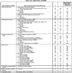
5. Structural System Coefficient (R):
The structural system coefficient, R is a measure of the ductility and over-strength of the structural system, based primarily on the performance of similar systems in past earthquakes. A higher number has the effect of reducing the design base shear. For example, for a steel special moment resisting frame the factor has a value of 8.5, while an ordinary moment resisting frame the value is 4.5. This reflects the fact that a special moment resisting frame is expected to perform better during an earthquake.
The values of R for various structural systems are found in UBC-97 table 16-N as shown on the image below.
6. Seismic Dead Load (W):
The dead load W used to calculate the base shear, includes not only the total dead load of the structures but also partitions, 25% of the floor live load in storage and warehouse occupancies and the weight of snow when the design snow load is greater than 30 pounds per square foot. The snow load may be reduced by up to 75% if its duration is short. The rationale for including a portion of the snow load in heavy snow areas is the fact that in these areas a significant amount of ice can build up and remain on roofs.
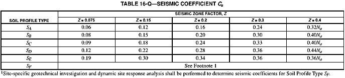
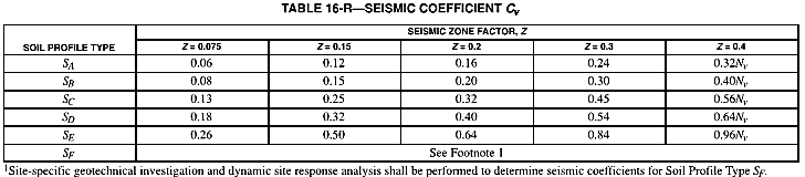
7. Seismic Coefficients (Cv and Ca):
The seismic coefficients, Cv and Ca are measures of the expected ground acceleration at the site. They may be found in Tables 16-Q and Tables 16-R of UBC code (see image below) respectively. The coefficient, and hence the expected ground accelerations are dependent on the seismic zone and soil profile type. Therefore they reflect regional seismicity and soil conditions at the site. Additionally, in seismic zone 4, they also depend on the seismic source type and near source factors Na and Nv. These factors reflect local seismicity in the region of highest seismic activity.
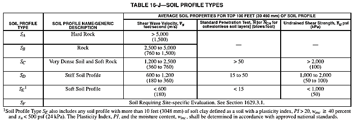
8. Soil Profile Types (S):
The soil profile type reflects the effect of soil conditions at the site on ground motion. They are found in the table16-J as shown on the table below and are labeled SA, through SF.
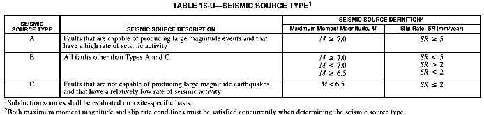
9. Seismic Source Type:
The seismic source type is used to specify the capability and activity of faults in the immediate vicinity of the structure. It is used only in seismic zone 4. The seismic source types, labeled A, B or C, are found in the table16-U below. They have defined in terms of the slip rate of the fault and the maximum magnitude earthquake it is capable of generating.
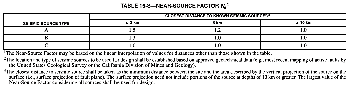
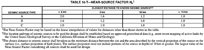
10. Near Source Factors (Na and Nv):
The near-source factors Na and Nv are found on the table 16-S and table 16-T respectively as shown below. In seismic zone 4, they are used in conjunction with the soil profile type to determine the seismic coefficients Cv and Ca.
11. Distribution of Lateral Forces (Fx):
The base shear V, as determined earlier, is distributed over the height of the structure as a force at each level Fi, plus an additional force Ft at the top:
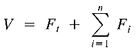
An additional force at the top is determined by:
![]()
where:
Ft= 0.07TV ≤ 0.25V if T≤0.7sec
Ft= 0 if T≤0.7sec
Ft accounts for the greater participation of higher modes in the response of longer period structures. The remaining portion of the total base shear (V – Ft) is distributed over the height, including the top, by the formula:
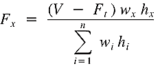
where:
w: weight at a particular level.
H: height of a particular level above the shear base.
At each floor, the force is located at the center of mass.
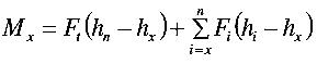
12. Story Shear (Vx) and Overturning Moment (Mx):
The story shear at level x is the sum of all the story forces Ft and Fx above that level:

The design must be checked as well according to the overturning moment at the shear of each level. The overturning moment at a particular level, Mx is the sum of the moments of the story forces above, about that level. Hence:
Except the above articles are based on the Uniform Building Code. You can furnish a copy here. Tell us your thoughts.
Leave your message in the comment section below. Feel free to share this article, subscribe to our newsletter and follow us on our social media pages.
[DISPLAY_ACURAX_ICONS]
Reference: 1997 Uniform Building Code (UBC-97)


what countries still using it?
Hi Yousef! UBC 97 is still widely used by some states in US and in the middle east. Some local codes use this as a basis in their respective seismic provisions as well.
Philippines is still using UBC97 as basis of our local code. Will move to ASCE seismic loading in he next update of the code this year or in 2022.
Pingback: Earthquake – Elevator Safety | Elevator Schmelevator
For the overturning moments, i would like to know more details like how we calculate the resistance of building at each level to these calculated overturning moments for each level and what are the code provisions for the factor of safety in this particular case.
Also do we have to use any particular load combination while viewing the results of these overturning moments in ETABS
Thank you for sharing – appreciate
builing within seismic zone 1, does this require seismic support per UBC97/ ASCE 7 exemption