

Perhaps the first thing for the Structural Engineers to be aware of in their structural design is the assumptions and consideration of the design loads. As Structural Engineers, we should be very careful assigning these loads to the structure we are designing for. Because these loads will dictate how heavy our structure is and the reinforcement and the size or dimension of each of the structural members will vary according to our load assumptions.
In this article, we will tackle how to calculate structural design loads on our structures and what considerations we need to do in order to achieve an economical design. At the end of this article, you will learn at least the basics of load and its load path, what are the considerations in assigning loads in a structure, and the load calculation procedure necessary at the start of Structural Design.
We all know that a given structure carries gravity and resists horizontal or lateral loads. In this article, we will focus on the gravity loads that a structure is carrying. Loads in structures/buildings are composed of the self-weight of the structures or the DEAD LOAD, the Super Imposed Dead Load or SDL, and the LIVE LOADS or movable loads. These loads are the basic loads of a certain structure/building.
These basic loads are carried by the slab which will be distributed in beams and transferred to the columns to be resisted by the footing which is rested on the underlying soil.
How are these Loads Calculated?
To understand how these loads are being calculated, Let us know first what type of material our structure will carry and how we will differentiate each accordingly. In a typical residential concrete structure, for example, the load of the building is to be carried by slab, we will start our calculation from there.
Dead Load (DL).
Dead Load is the self-weight of the structure. To calculate dead load, the density or unit weight of the structure should be multiplied by the thickness, which will give us the weight of the structure per given area.
For a concrete slab of 0.25m thick for example, that will give us the following:
Considering the unit weight of concrete to be 25kN/m3,
- 25 kN/m3 multiplied by 0.25meter = 6.25 kN/m2.
Superimposed Dead Load (SDL).
Superimposed Dead loads include the partition or interior walls, floor screeding, floor finish, ceiling loads, and MEP pipes and fixtures. To calculate, let us assume that a slab is carrying a total of 6 kN/m2.
*Note that the same principle as calculating dead loads can also be adopted in determining the weight of the Superimposed Dead Load making up the construction, with the given density or unit weight of the material. These densities or unit weight of materials can be sourced from the relevant codes and standards, material data sheets, or obtained via laboratory testing.
Live Load (LL).
Live Loads are the movable or moving loads that the structure can carry. It can include the movable equipment, movable partitions, furniture, and the people occupying the Structure. Live load assumptions depend on the usage of the building or the type of occupancy. It has obviously bigger live loads in assembly or gym areas compared to the residential areas.
The minimum live load requirement is given in the codes and standards that we are using. Referring to ASCE 7-16 for example, Table 4.3-1 will give you all the recommended live loads of the structure being designed.
Let’s take the Live load to be 2 kN/m2;
So our loads/imposed loads on a residential concrete structure can be summed up to:
- Dead Load/Self Weight = 6.25kN/m2
- Superimposed Load= 6 kN/m2
- Live Load= 2 kN/m2
How the Basic Load is Being Distributed in the Structure.
Before we proceed, you have to differentiate whether our slab is a One-way or a Two-way slab. Refer to our previous article, one-way vs two-way slab, to know more!
To distribute the loads let us consider the result of the Loads that we previously calculated:
- Total Dead Loads (e.g., self-weight and SDL)= (6.25+6) kN/m2 = 12.25 kN/m2
- Total Live Load = 2 kN/m2
The Dead Load, Superimposed Dead Load and Live Load that we consider will be carried by the slab. It will then be distributed to the perimeter beam supporting it. To distribute it on the perimeter beams, let’s take a look at this figure.
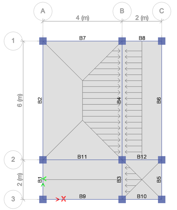
To distribute the load on a two-way slab, simply draw an isosceles triangle in its short direction and a trapezoid in its long direction as shown. A one-way slab simply cuts the slab into two along its length. For the beam to carry the slab, calculate the areas adjacent to it. Let’s calculate the loads on beams B3 and B4 respectively as an example.
- Area of the triangle at B3
A= 1/2bh = 1/2(2×1) = 1.0 m2
- The areas adjacent to B4 = area of trapezoid plus area of the rectangle
Area of Trapezoid= (a+b)/2 x H = (2+6)/2 x 2 = 8.0m2
Area of Rectangle= LW = 6×1 = 6.0m2
A total = 8.0 + 6.0 = 14.0 m2
To distribute it along the beam, multiply these areas with the Dead Load, Superimposed Dead Load, and Live load to get the actual load distribution in kilonewton.
- For B3:
DL= 12.25 kN/m2 X 1 m2 = 12.25kN
LL= 2 kN/m2 X 1.0m2 = 2kN
- For B4:
DL= 12.25 kN/m2 X 14 m2 = 171.5kN
LL= 2 kN/m2 X 14m2 = 28 kN
Dividing the actual load distribution into the length of the beam will give you the uniformly distributed load in kilonewton per meter.
- For B3:
DL= 12.25kN / 2m = 6.125 kN/m
LL= 2 kN / 2m = 1.0 kN/m
- For B4:
DL= 171.5kN / 6m = 28.58 kN/m
LL= 28 kN / 6m = 4.67 kN/m
To use in design these service loads should be multiplied by the ULS factor, 1.2 for Dead Loads and 1.6 for Live Loads. The load reactions on each support of the beam will be carried by the column joining them and eventually transferred to the footing supported by underlying soil.
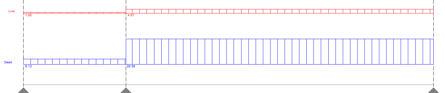
Uniformly Distributed Load in Beams B3 and B4
The figure above shows the calculated uniformly distributed load on beams B3 and B4. Check out our next article on how to design these beams by subscribing to our newsletter and other social media pages below.
What do you think about this article? Let us know your thoughts! Leave your comment below. Please like, share, and subscribe for more.
[DISPLAY_ACURAX_ICONS]


You made an interesting point when you talked about how structural engineers need to be careful when assigning loads to a structure. I would imagine that it would be important for engineers to inspect a structure on a regular basis after the construction is completed. It seems like inspections would play a role in making sure that the building continues to maintain the weight load properly.
Hello there! Thank you for your straightforward explanations. I have done load calculations before, about 10 years ago, so I am very rusty. I do have one question about the calculation for B4. Why is the DL 14 m2 and the LL 1.4 m2? That one has me stumped. I honesty thought they would be the same for both. Can you please explain why they are different. I don’t understand.
I believe that is a typo. Should be 14m2 for both
I,very interested to your explanation please add more to the bigger structural engineers
you know about escalator load calculation where upper portion rest