
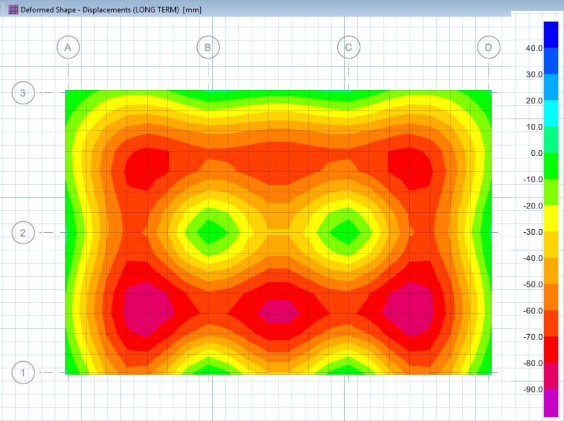
Long Term-Deflection in slabs/beams is the deflection or the deformation that occurs over time due to shrinkage and temperature. It is also influenced by the condition of the cracking before loading, then creeping, which depends on the time passed to the time of the first loading, the environment, and other factors.
In this article, we will focus on the analysis of long-term deflections on slabs.
Analysis of Long-term deflection of the slab using SAFE program is often confusing especially for those newbies in structural design, but that’s already a few steps away of knowing. This article will guide you with easy to understand step by step on doing slab’s long-term deflection analysis using the SAFE program. Before we proceed further, let us define the following parameters used. As we commonly encountered in the design, DL stands for dead loads, LL designates the live loads and SDL denotes superimposed dead loads.
In SAFE, the following principle may apply on the modeling; LONG TERM DEFLECTION– is the sum of immediate deflection for 75% Live load, (DL+SDL+LL) – (DL+SDL+0.25LL) and Long-Term Deflection for DL+SDL+25% Sustained Live Load. Which means:
Long-term Deflection = 75%LL (immediate effect) + 25% LL+DL+SDL (long-term effect).
But, how to apply these principles to the SAFE program? Supposed that we had already a SAFE model of the slab that we are going to analyze and ready to run. The next procedure is listed as follows:
Below are the procedures for applying the above principles of Long Term Deflection Analysis:
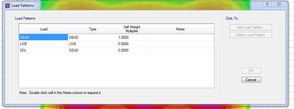
1. Defining a Load Pattern:
- Go to Define>Load Patterns
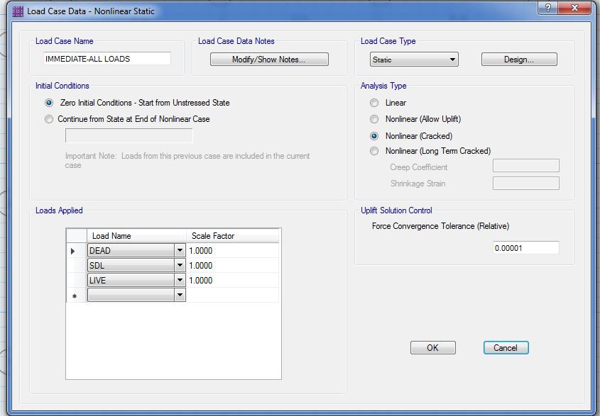
2. Define a Load Case for Immediate All Loads
- Go to Define>Load Cases>Add New Case > tick nonlinear (cracked) for the analysis type
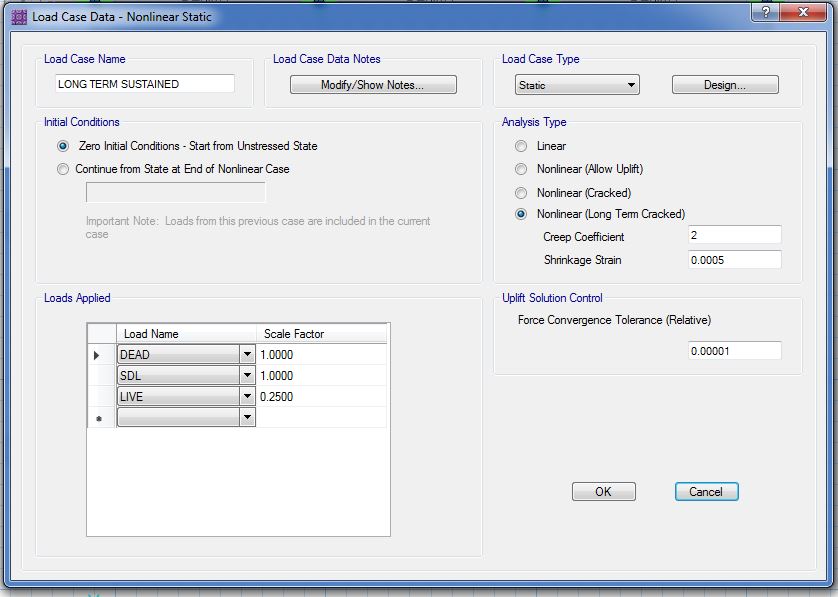
3. Define a Load Case for Long-Term- Sustained
- Go to Define>Load Cases>Add New Case > tick nonlinear (long-term cracked) for the analysis type
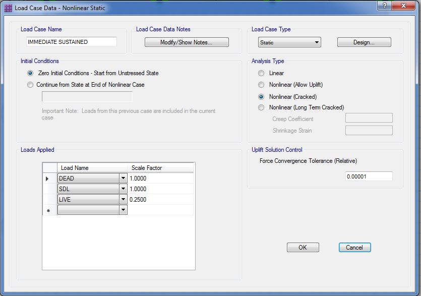
4. Define a Load Case for Immediate-Sustained
- Go to Define>Load Cases>Add New Case > tick nonlinear (cracked) for the analysis type
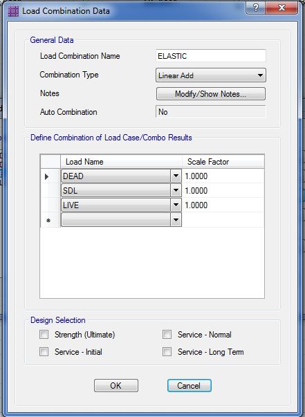
5. Define Load Combination:
“Elastic”-to display elastic deflection for service loads.
- Go to Define>Load Combinations>Add new combinations
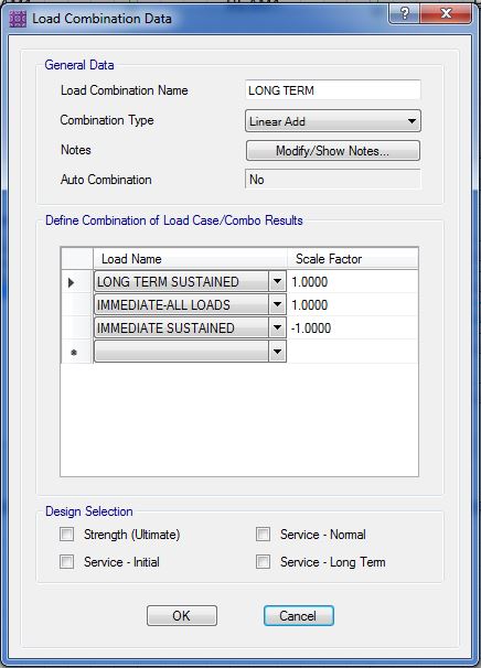
6. Define Load Combination:
“Long Term” – this is to combined 3 load cases for long-term analysis principle.
- Go to Define>Load Combinations>Add new combinations
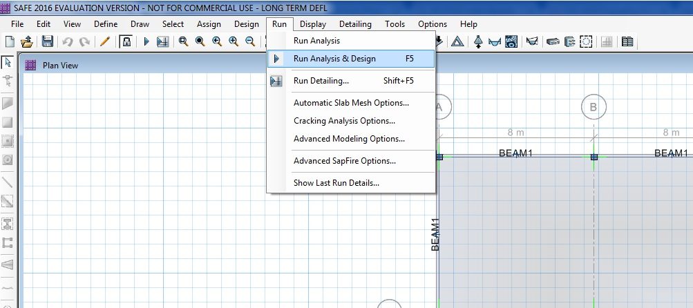
7. Run Analysis.
- Go to Run>Run Analysis & Design
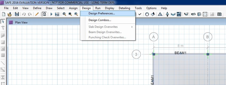
Be sure to check the design preferences and edit the design parameters accordingly.
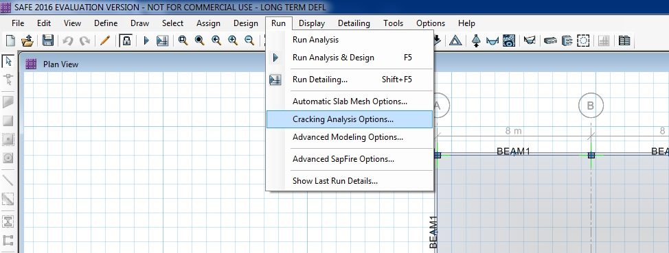
As well as the Cracking Analysis Options.
Check out the video presentation below on how the long term deflection is being performed in SAFE. Please subscribe to our youtube channel for more structural software tips like this!
Incremental Deflection Vs Long Term Deflection
Incremental Defletion occurs after the Superimposed Dead Loads (SDL) has been put in place. This also includes the deflection due to its own weight. To check in SAFE program. Define another load case for Dead load plus the Superimposed Deadload (DL+SDL). Then substract the added load case from the long term deflection’s load combinations we discussed above.
What are your thoughts on the procedure discussed above? We’d love to hear from you. Leave your message in the comment section below. Feel free to share this article, subscribe to our newsletter and follow us on our social media pages.
[DISPLAY_ACURAX_ICONS]

I have some remarks on the article, and I think they are important to younger engineers.
Right at the beginning, a sentence was written that was wrong
Cite ” Long Term-Deflection in slabs/beams is the deflection that occurs over time due to shrinkage and temperature”
Long-lasting deformation also depends on the condition of the cracking before loading, then cracking, which depends on the time passed to the time of the first load, the effect on the environment and on a whole range of factors. All I’m saying is to avoid confusion for the novices.
Thanks, Mr. Velimir for pointing out, we incorporated your remarks on the article.
what is the role of soil subgrade reaction in these calculation ?
No subgrade reactions to consider in the Long Term Deflection analysis. Subgrade reactions are usually considered in raft/mat foundations design.
Dear Sir
I’d like to know when we can consider the slab and a restrained or un-restrained slab.
in Other words the tension stress of concrete to be 0.33 or 0.62 root square Fc’
instead of creating two load cases that is immediate all lodas(DL+SDL+LL) and immidiate sustained for 0.25LL case (DL+SDL+0.25LL) , why cant we create only one load case with 0.75 LL. i.e. DL+SDL+0.75LL.
please clarify
I think the principle of superposition does not apply during nonlinear analysis. so, the load case with 0.75LL (DL+SDL+0.75LL) isn’t going to be equivalent to the (case 1 -case 2).
Note:
Case 1: immediate all lodas (DL+SDL+LL)
Case 2: immediate sustained for 0.25LL case (DL+SDL+0.25LL)
Hi Raj!
We need to separate each load cases because aside to the fact that each cases has its own load combinations, each has a different analysis type as well.
please clarify this point in detail
Thankyou
That was a very useful explanation for assigning long term deflection. I would be thankful if you uploaded a video illustrating the steps of calculations of raft foundation against water uplifit force including piles and without piles.
Thanks str.abuzour! Our youtube channel actually featured Raft Foundation Design. The only difference is that you have to add the hydrostatic load to it, the rests are basically similar procedures. Refer to this link for your reference: https://youtu.be/A2uo6fn149M. Kindly consider subscribing to our youtube channel as well for more videos like this.https://www.youtube.com/c/TheStructuralWorld?sub_confirmation=1
INFLUENCE OF CRACKS ON REINFORCED CONCRET, WHAT IS SPECIFICALLY RELATED TO FRAME STRUCTURES
CHAPTER-1
Abstract:
There is a clear inconsistency in the metod of calculation of reinforced concrete constructions. We enter a full concrete section into computer, than we make a calculation and then we enter the effects of; cracks due to load, shrinkage and creep. As the distribution of forces is calculated according to the rigidity, we get a mistake, right at the beginning of the calculation. The rigidity of each element of the structure is significantly different if we take a homogeneous concrete section or the same section with cracks. (For the sake of simplicity in the ACI code, reductions are indicated, especially for beams, columns, plates e.t.c. but there it also writes “if it is not specified, these reductions can be taken”. Eurocode takes only a reduction for earthquake load, and it is 50% for all elements, which is really astonishing.)
It has its historical course, which is not from ignorance, but a simpler calculation in practical work. The usual procedure for modeling frame structures in high-rise buildings is that of full concrete, meaning homogeneous joints for beams and columns. As reinforced concrete, in order to use it, actually has cracks.
INFLUENCE OF CRACKS ON REINFORCED CONCRET, WHAT IS SPECIFICALLY RELATED TO FRAME STRUCTURES
CHAPTER-2
Reduction of stiffness is not the same for each element of the cracks in construction. However, the two same beams in reality do not have the same cracks, so the reduction factor can not be the same for all beams and is also the main reason why I write this article. So in the start of calculation we enter false value . The consequence is that we run, often very complex calculations , worrying about accuracy, although we know that initial input data is wrong. All the present simplifications can be alleviated if we consider the cracking of the gap between the cracks.
In reality, for example, the beam has a different stiffness at each site throughout its length. At the site of the crack, it is significantly smaller, but between the crack is a full concrete section. So for the given distance (20-25 cm), the computer can calculates stiffness, and then with numerical integration, the global stiffness of the entire beam, ie each element in the structure, is reached.
We can add that the elements without cracks, due to the contribution of the steel, also have a higher torque moment than the one in which only the concrete is considered, so there is actual difference between the reality. As a result of the calculation, the wrong amounts (impacts) are obtained and the recorded state is even greater. In contrast to this, due to aging concrete, the neutral axis deepens (grows), and thus the resistant moment grows. The ratio between the homogeneous and the broken section, which has increased as a result of the reinforcement, over time decreases. In any case, there is a significant difference if all elements are treated equally or we respect realistic weaknesses
The displacement of nodes, and thus errors, is due to all vertical and horizontal loads. Furthermore, the error also extends to the calculation of the oscillation period, and thus to the earthquake force, as well as the overall size of the frame shift.
INFLUENCE OF CRACKS ON REINFORCED CONCRET, WHAT IS SPECIFICALLY RELATED TO FRAME STRUCTURES
CHAPTER-3
How I imagine the proces of calculation :
1. We input full cross section, and determin how wide crack can be, what defflections is alowed and so on. According to some national codes.
2. Computer make first pass in which forces and reinforcement is raughly calculated. According to results for each member, stiffeness is determin, with numerical integration.
3. In second pass, computer repeat the procedure and check if everything from input is satisfyed
4. If not, again procedure is repeat
5. When everything from input is satisfyed, computer stop, and give as the result in which all demands are obey, but in some conditions ( for example ; in some member rebars must not be greater then some profile).
6. We either corect it manualy, either with computer, which make last pass.
7. Shrinkage can be involved in the same way if we want to.
8. We have much better outcome
9. Today, machines are very fast, and we can determin limitations of iterations. If result between two last passes are not different more the 3,or5 or7% machine can stop.
INFLUENCE OF CRACKS ON REINFORCED CONCRET, WHAT IS SPECIFICALLY RELATED TO FRAME STRUCTURES
CHAPTER-4
The discussion about this has been on Linkedin for a long time. I did not succeed in convincing a sufficient number of engineers, but two great software companies showed interest and then dropped, because a small number of engineers who accepted it. I will not mention the names.
My statement is that:
1. reduction must be involved
2. This is the job for computer
3. It will be done by numerical integrations for each member
4. If ignored, we are starting from wrong positions
My wish was to inform you about it, to make a mistake and to think it needs to be corrected and how it can be done.
I would like the discussion to be public.
Kind Regards
Velimir Kazic
Hi Velimir! This is an interesting topic to discuss. We maybe consider an article like this to post on our website with option to feature you as a contributor. Just keep us posted. Cheers!
liked
Dear sir
I have a problem with a flat slab, in longterm deflection, its deflection is 32mm in 8m clear span how can I decrease it without increasing the thickness?
Hi Saifullah! If increasing the thickness is not an option, you can try to provide a hidden beam to minimize the deflection.
Dear sir,
Thank you for such detailed and simplified tutorial.
However i have a concern, does SAFE considers reinforcements when it calculates deflection?
Thanks in advance
Regards
Yes, It can. You can input the effect of the reinforcement through RUN>Reinforce Option for Cracking Analysis and Input the reinforcement ratios for compression and tension reinforcing. Do this exercise and check whether it has a significant effect on the deflection result.
Dear sir ;
I would like to ask about the minimum As for ribbed slab (waffle slab) in safe is 0.18*total depth of slab while this ribbed slab has voids (not solid as a flat slab).
Please clarify to me.
thanks!
Whether SAFE considers the multiplier lambda as per ACI 318/ ACI 435 while calculating long term deflection. If so what’s range of value it considers…
Hello,
Can u please tell me what property modifiers should be assigned for slabs while checking long term deflection?
Regards
how to know the allowable long-term displacement for footings? Can you give us the interpretation of the values gathered in long-term deflection? thank you
We don’t check the footing for LTD, instead, we are checking the soil pressure generated by SAFE against the recommended SBC under service loads combos.
Is there a way to click on a specific spot of the deformed shape and permanently display the deflection at that point for the Loading combination?
When I do the analysis the program gives me deflection with one color although I’m sure about the loads on the slab and the combinations?!
Check your contour range and set the min and max to zero (0).
where this Load Combination for Long Term deflection is mentioned ?(Code book and Clause no.?)