

The slabs or suspended slabs initially carried the design loadings of the structure. Its design loadings is depending on the occupancy of the building we assigned at the start of our design. These basic loads’ such as Dead Load (DL), Superimposed Dead Load (SDL), and Live Load (LL), carried by the slab will then be distributed to the perimeter beam supporting it and eventually resisted by the footing underneath upon transferring to columns. In structural design, differentiating the difference between the two is an important step, to begin with.
Comparison Between One-Way and Two-Way Slabs
1. Slab Classification
To distinguish one from the other let us calculate the ratio of longer span (L) to shorter span (S) of the slab.
The slab is a one-way slab if;
L/S > 2.0
On the other hand, the slab is a two-way slab if;
L/S ≤ 2.0
Considering the formula above, Figure 1.0 below shows the slab classification as shown:
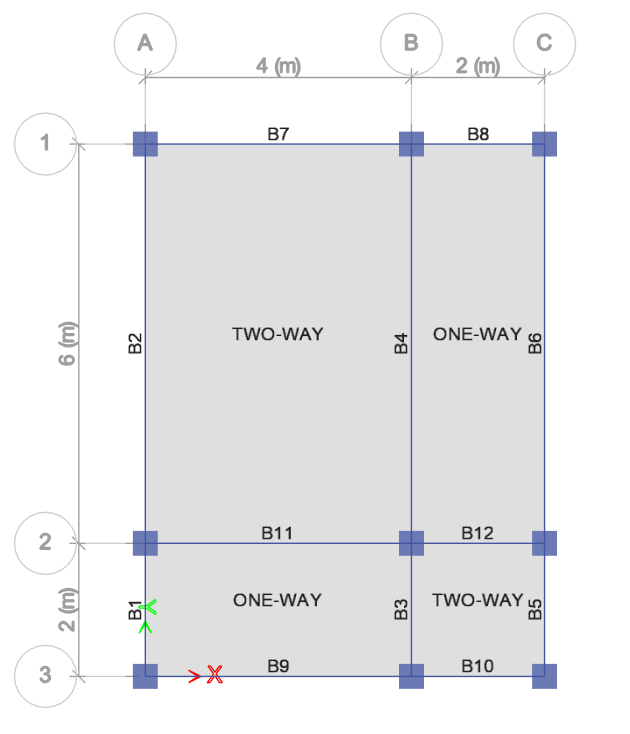
Figure 1.0 Slab Classification
2. Load Path Transfer and Bending
One-way slab transfers the imposed loads in one direction only or in two edges to the perpendicular beam or walls. This tends to bend the slab in a short direction only.
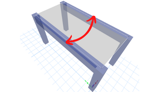
Figure 2.1 One-Way Slab Direction of Bending
The two-way slab has four edge support. It is supported by beams or walls on all four sides in which the bending occurs in two directions of the slab.
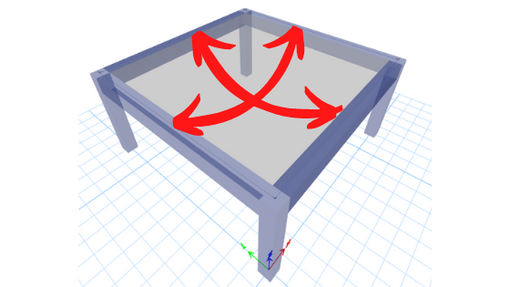
Figure 2.2 Two-Way Slab Direction of Bending
3. Equivalent Loading Distribution
A one-way slab simply cuts the slab into two along its length forming a rectangle as shown in Grids B-C/1-2 and A-B/2-3 of Figure 3.1 below. To distribute the load on a two-way slab, simply draw an isosceles triangle in its short direction and a trapezoid in its long direction as shown on the rest of the slab below.
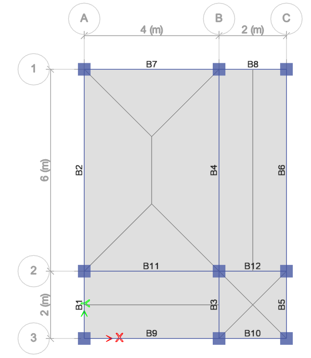
Figure 3.1 Equivalent Loading Distribution
The loads on the slab will be transferred to the beam as shown in Figure 3.2. For the beam to carry the slab, calculate the areas of the slab adjacent to it. The areas will be multiplied by the basic loads (DL, SDL, and LL) which we initially assigned at the start of our design.
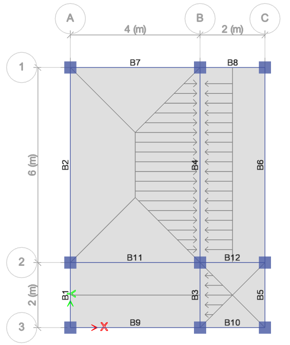
Figure 3.2 Load Distribution Diagram
4. Steel Reinforcement Distribution
The main reinforcement of the One-way slab is laid along its short direction as shown in Figure 4.1, on the other hand, the two-way slab’s main reinforcement is provided in both directions as per Figure 4.2.
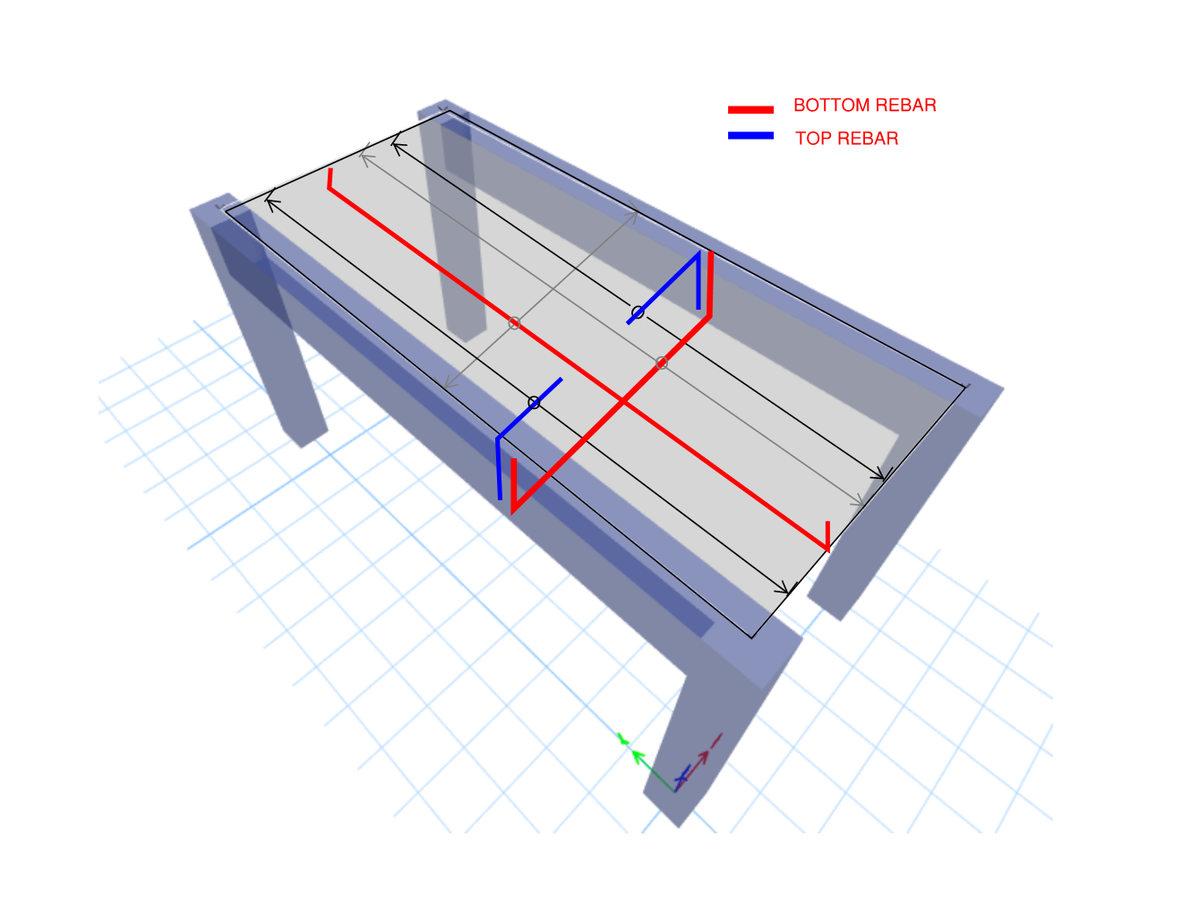
Figure 4.1 One Way Slab Reinforcement Distribution
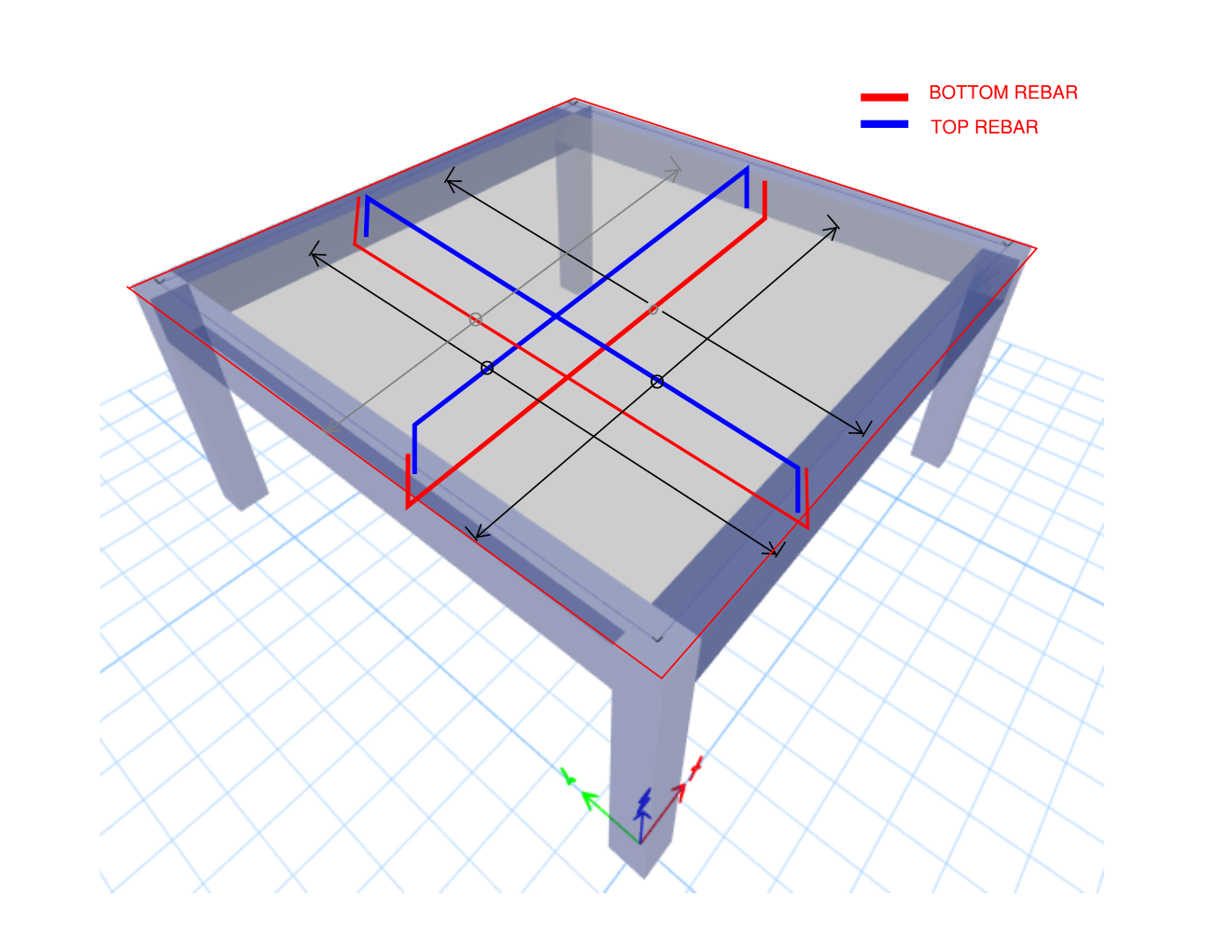
Figure 4.2 Two Way Slab Reinforcement Distribution
What do you think about this article? We love to hear your thoughts! Leave a message in a comment form below. You can also follow, like, and subscribe to our social media pages below to be updated with the latest posts.
[DISPLAY_ACURAX_ICONS]


Good knowledge about our field related
It’s a an elaborated explanation. I recommend lecturers in schools should go this length of exposing the students in structural design.