SAFE by Computers and Structures Inc. (CSI) is a powerful tool in Slab Analysis using finite element method or finite element analysis (FEA). In this particular software, you can design and analyze the horizontal members of a building not only the slabs and each type, but also the beams and different types of foundations from isolated, combined, strip, raft, pile caps, and others. Whether those are reinforced and post-tensioned concrete, SAFE has “no sweat” analyzing it.
The most likely behavior of these elements that we are analyzing for depends on how we modeled it. To come up for the design results in the SAFE program, the key is that we should model the design strips. Without this, we can see no design results of the element we are analyzing. Design strips will determine the number of bars we need in a particular area. This is also essential not only for getting the number of reinforcing bars but also in getting the output results of the stresses like the shear and moment values and the diagrams of the particular member. All of these can only be done by the proper definition of our design strips so we can arrive in an accurate result of the analysis.
At the end of this article, we will learn the proper way of defining design strips using the SAFE program. We will show you how to model it correctly and gives you some tips of advice to achieve a convincing result.
Defining Design Strips
After the modeling stuff has been done, we can now proceed to the analysis and design part. But before we go running an analysis, we should create the design strips for us to be able to come up with the design result. Here is how:
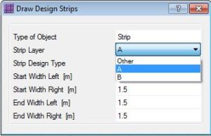
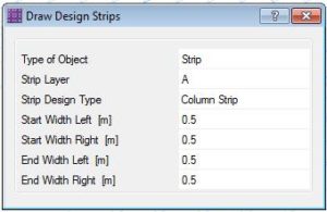
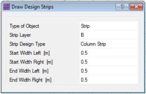
- On the SAFE screen interface, Go to Draw>Draw Design Strips or click the Design Strips icon on the left side of the screen. The “Draw Design Strips” form will appear as shown on the image on the left side below. In this form we can assign the parameters we are defining. Like when you click on the Strip Layer, the types of Strip Layer “A” and “B” will appear as shown in the image on the right side below. Letter “A” and “B” represents the direction of the strips or the strips in X and Y directions, “Others” corresponds to other types of strips other than A and B.
2. Defining the Design Type and Width of the Strips
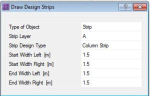
On the same form, “Draw Design Strips”, click on the Strip Design Type and assign as column strip. As per the author experience, there is no issue of using the column strips all the way. This is also a convenient way of modeling design strips if you are using only one type of design strips. The most common width of design strip to use is a one-meter strip because you don’t have to worry about the result itself as it is already according to one unit. You can use any width of design strips depending on how wide the project is to save time in running and analysis, but don’t forget to divide the results with the width of the strips you use to get the result in 1-meter strips. If you decided to use a 1-meter strip the right inputs on the Draw Design Strips form are showing on the image below.
3. Drawing of Design Strips in Plan
There are two ways to draw the design strips in a plan, either use the replicate command or draw it manually. The most common technique is to draw a typical strip and replicate that on the desired area or the whole area of the slab we are analyzing. Before replicating be sure that the parameters, has been defined accordingly as shown in the image below. Click the design strip that we made and right-click to display the Strip Object Information as shown below.
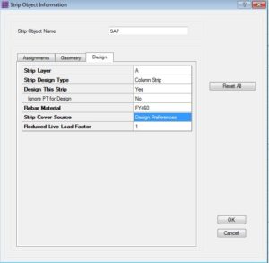
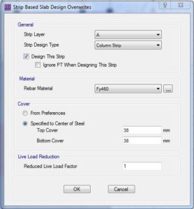
Design preferences as highlighted on the previous form can be elaborate in detailed. This is usually used for the bars with two or more different layers of extra bars. Click the Design Preferences as highlighted in the previous form and the Strip Based Design Overwrites form will appear as per the image below. From there we can specify the concrete cover from the center of the steel either from the top and bottom locations.
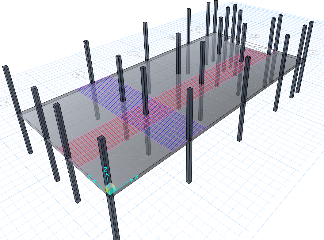
4. Drawing the design strips in X-Direction (Strip Layer A) and Y-Direction (Strip Layer B) on the plan.
Before drawing the design strips, In Strip Object Information as shown on the previous image, make sure that the Strip Design Type has been selected as “A” and draw design strips in X-direction. You can select the design strip that you draw and replicate it along the width of the slab you are analyzing. On the other hand, draw design strips along Y-direction by selecting “B” on the Strip Design Type and replicate accordingly.
Drawing the design strips manually usually done on an irregular shape slab, but make sure that the stroke on how you have drawn is on one direction only, e.g. if you start to draw it from left to right then you have to draw the other strips from left to right again and vice versa.
Here is a youtube video showing how to create design strips in a SAFE program: How to Create Design Strips in SAFE
After the design strips have been defined we can now perform the Run>Run Analysis and Design. This time we can now see the design result of our SAFE model. But how can we interpret these results? You can refer to our next article on how to interpret design result in SAFE. Sign up on our newsletter for any updates.
Tell us about your thoughts. Leave your message in the comment section below. Feel free to share this article, subscribe to our newsletter and follow us on our social media pages.
[DISPLAY_ACURAX_ICONS]


hi, my safe 8 does not have edit design strip option. I do not know how to make design strip in my foundation model. pls assist.
Thanks in advance
Hi Varshavian! Defining strips in SAFE 8 is different from the latest version of SAFE. You can define the strips in SAFE 8 by clicking view> X strip layer from there you can select the slab. To make the strip having a uniform width, delete all the slabs layer except the bottom part and edit the strips coordinate by right-clicking on the slab, then edit>replicate that strip to cover the whole slab. You can do the same in Y direction strips. Cheers!
Halo Admin, If you use 1m witdh strip, the adjacent column/wall has too much reinforcement (large bending moment) because of concentrated stress/moment. How do you overcome this issue ? Thx
Hello Hiep Nguyen, try to release the moment along the slab edges and see what will happen.
Hello Admin. Can you please clarify following doubts.
1. Can I draw strips in both X and Y directions under strip A ?
2. In the raft, there are thickening under the columns and regular thickness in between the columns. (e.g. Thickness of raft under column for the perimeter of 2 meter is about 0.75 meter and in between columns, thickness is around 0.3 meter).
Considered mesh is T 16 @ 200 c/c. However, extra reinforcement required at top in 0.3 meter thick raft is around 2000 sq.mm. Which is too large.
Can you please explain/ clear my doubt about this higher reinforcement ?
Hi Purnachandra
1. Yes, you can draw strips at x & y direction under strip A. But that is not advisable, the problem is that it will be hard for the designer to interpret the results because doing that will result in a reinforcement congestions as it will show reinforcements in both directions. Doing it in different strips is easier to interpret as you have always an option to see the x or y-direction separately and an option to show both directions at the same time if you like.
2. It is expected to have those extra reinforcements at the top. There are a lot of reasons why this is happening, the most common is that maybe your column to column distance is too far or the loads under columns with thickening raft are huge that will create a larger negative moment. It is worth a try to increase the 0.3m thick raft and see if it will lessen the extra top reinforcements.
Cheers!
Thank You…
You are welcome Purnchandra. Thanks for dropping by!
Hi. Should I unselect middle strip option and how can I release moment at slab edges
Can you clarify why do you need to unselect the middle strips? To Release the edges: Select first the slab edges that you want to release and go to Assign> Slab Data> Edge Releases and Select Releases, Vertical Displacement for Shear or Rotation About Slab Edge for the moment.
Hi dear sir
How I can model footing slab and grade beam at the same level in the SAFE program?
Hi Saif. In SAFE modeling we cannot consider the difference in levels, so you can model footing slab and grade beam at the one level.
Hi.when we move along a design strip safe shows top and bottom reinforcement that changes. Now, what value we should use for reinforcement of that strip?
thanks a lot.
Hi Majid. Check out this video on our youtube channel on how to interpret the top and bottom reinforcements in a slab design. https://youtu.be/trzq2PgX-14
After providing values in Draw Design window midpoint option in not showing on footing for drawing design strips. How to enable for midpoint.
You need to turn the snap On, shift + click for options.
can you please explain for 1m wide strip what we have to define either 0.5m strip while drawing the strips or 1m we have to keep.
Hi
if i m modeling a ribbed slab the width of the design strips in the ribs direction should be equal to the bf of the rib?
Yes, it can be.
An excellent blog! Thanks for this valuable knowledge!
How can We Further Increase our Knowledge in Structural Design and follow good practices such that we can design safe and economical structures? Please recommend some Resources to increase our practical knowledge, apart from your blogs of course 🙂 that is actually required and become successful in this field!
IN SAME DIRECTION, CAN THE DESIGN STRIP WIDTH BE OVERLAPPED?
WILL THERE BE ANY ISSUE?
Better not, or else it will give you two results.
If we can use only column strips what are middle strips for? In your experience would you use only column strips? F.E. If you have a slab 10 x 10, would you put 10 column strip on one axis and 10 on the other as well? (or 1 at the end divided it by 10 right?)
Hello Admin, when we build a safe model with beams and slabs, we can get the design forces by strips, then can we use the beam forces exported from safe model to design the beams?
Yes you can!
having problem with “measure line” under tab view but no dimension of footing appearing rather a thick line blinks for a while in csi safe v21.2.0
Hello
why I should do the design strips for my model ? What is the result will be if I ignore doing it?
Hi, So you can design the steel reinforcement.