Choosing the right load combinations in structural design is necessary for structural design. As this may dictate the outcome of our design. Too many load combinations may result in an over design outcome, thus it can compromise the economic aspect of the projects. The right load combinations will, of course, provide us the effective results that may not compromise the soundly and economical aspects of the design.
With reference to ASCE 7-10 section 2.3.2 and UBC 97, just like any other code used in building design, the two mentioned code set standards according to the following basic load combinations presented in Table 1.1 and Table 2.1 below. But did you know that these load combinations had a lot of provisions that maybe we don’t know yet? This article aims to summarize the provisions made by ASCE 7-10 and UBC 97 code for the readers/ structural design engineers to easily determine which one is going to consider or being omitted in the design load combinations during our structural design.
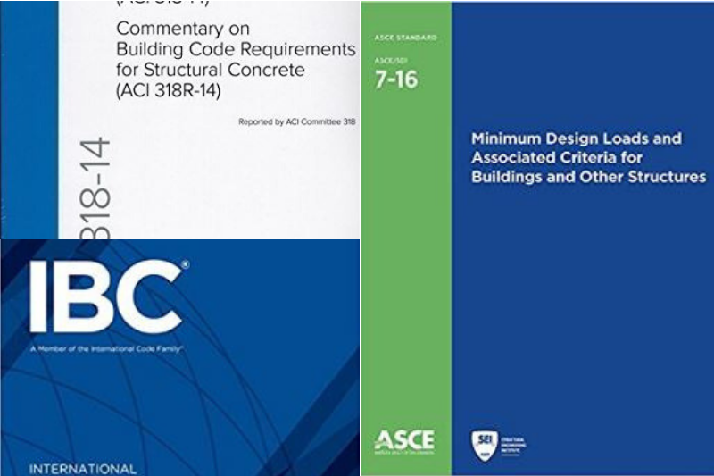
For a clearer understanding on the notations, kindly use the actual ASCE 7-10 and UBC 97 code. If you don’t have a copy yet, kindly visit our code section.
Points and Design Considerations:
1. When using the ASCE 7-10 Code
With reference to basic load combinations as per Table 1.1 below:
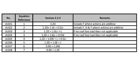 Table 1.1 Basic Load Combinations (ULS) as per ASCE 7-10 section 2.3.2
1.1 Load factor on Live Load, L
The load factor on L in combinations 3, 4, 5 is permitted to equal 0.5 for all occupancies in which Lo in table 4-1 is less than 5kN/m2, with the exception of garages or areas occupied as places of public assembly.
1.2 Effects from Wind and Earthquake
The effects from both wind and earthquake loads shall be investigated where appropriate, but they need not to be considered to act simultaneously.
1.3 Structures under Seismic Design Category
For structures assigned for the Seismic Design Category (D, E or F) + SDS bigger than 0.125, consider the seismic design combinations as per section 12.4.3.2 as follows:
- (1.2 + 0.2 SDS) D + ρQE + L
- (0.9-0.2 SDS) D + ρQE + 1.6H
where: ρ is equal to 1.0 and 1.3 for seismic design categories A, B, C and D, E, F respectively.
1.4 Orthogonal Effect Considerations
For the non-parallel system or simply shear walls not parallel to x and y plan or structures under C, D, E & F design category, then an orthogonal effect shall be considered as follows:
- 1.2D ± Ex ± 0.3Ey + L
- 1.2D ± 0.3Ex ± Ey + L
1.5 Presence of Planted/Floating Columns
In case of floating or planted column or the system is cantilevered, consider the following design combinations with reference to section 12.4.3.2.
- (1.2 + 0.2SDS) D + ΩOQE+L
- (0.9 – 0.2 SDS) D + ΩOQE+1.6H
2. When using UBC-97 code
With reference to basic load combinations as per Table 1.2 below:
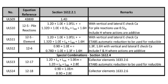
Table 2.1 Basic Load Combinations (ULS) as per UBC 97
2.1 Considering Construction Sequence
When the construction sequence using ETABS or other design software is understood and the project may benefit from the early termination of dewatering. Do not include SDL in the above combinations for the calculation of pile tensions, when considering only vertical loads, combinations including lateral loads should include SDL.
2.2 Vertical and Lateral Earthquake Components
The vertical and lateral components of force due to the earthquake are to be included in the ULS (11) combinations above, as per UBC 97, 1630.1.1.
Where:
-
-
- E = ρEh +Ev
- Em = ΩEh
- ρ – Redundancy factor, to be taken as 1.0
- Ev equal to an addition (or subtraction) of 0.5CaIeD to the dead load effect, D, for Ultimate Limit State, and may be taken as zero for Allowable Stress Design
-
2.3 Auto Construction Sequence
Auto construction sequence only replaces the components specified in design combinations, for review of pile loads or similar the engineer needs to manually create a service load combination, i.e. SLS = D + W + H = AUTOC + 0.5SDL + FAÇADE + W + H.
What do you think about this article? Any considerations that we missed? We love to hear your thoughts! Leave a message in a comment form below. You can also follow, like and subscribe to our social media pages below to be updated with the latest posts.
[DISPLAY_ACURAX_ICONS]