

Before we proceed with the design proper and after a model is analyzed and was completed in ETABS it is very important to check whether the basic characteristic of the model matches the expected behavior of the building or not. Doing so is fulfilling to know that our model is geometrically and analytically sound. If the ETABS modeling had 3 Major Checks before the Analysis that needs to consider, there are also post checks analysis to be done accordingly. Refer to the three major checks that the designer needs to consider right after the analysis.
1. Analysis Log and Results
1.1 Warning Messages
In the previous article, ETABS’ 3 Major Checks before Analysis and Design, the author recommends checking our model from any warning messages. A post checks on warning messages should also be taken into consideration as for some reason it may also be generated after the analysis, like errors on the load transfer and the like. A warning is produced during the solution of equilibrium in ETABS when there is an error in the calculation of finite element stiffness matrices, boundary condition or applied loading. If you come across warning messages for the solution along any degrees of freedom, you will need to locate the points and check for any potential errors. This may be caused by adjacent points forming a discontinuous mesh, free end support and, others. These warnings may be removed by reshaping the objects, defining appropriate boundary conditions or supports and any other suitable action that ensures a sound analytical model.
1.2 Model Instability
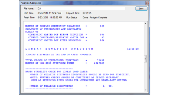
A post model instability should also be considered in post checks analysis as for some reasons, instability may again be a problem. As designers see to it that our model is once again stable and no ill-conditioned message appears. For stability, the number of negative stiffness should also be zero and the negative eigenvalues should also be zero as shown in the screenshot below. Otherwise fixing the model stability is a must. How? Refer to ETABS Instability Messages.
2. Deformed Shape and Model Animation
The deformed shapes mimic the behavior of the building according to certain load conditions. After the analysis, it is recommended for the designer to investigate the deformed shape of the structure specifically under static loads. This may be done by animating the structure for the required load case and should be matched with the expected behavior of the building. Scale factors may be used to examine the response spectrum. A working procedure on how to perform scale factors in ETABS will be published soon.
3. Modal Characteristics
The mode shape results of the model will give us a good insight into the dynamic characteristics of the building. The model analysis is initially investigated to determine the elastic periods and mode of vibration. Usually, the first three modes (translation in x and y direction and torsion) of vibration are of particular concern since they include most of the dynamic response, however, this should be verified by investigating the modal participation factor. For example, if torsional mode shows a higher participation factor, then a revised in structural framing will help to minimize the torsional effect.
This can also be determined by examining the movement or rotation of the building by animating the deformed shape under Modes 1, 2 and 3. Another way is that, comparing the results of the first three (3) modes of RZ againts UX and UY refering to Modal Participating Mass Ratio table of Figure 3 below. Ideally, if RZ is less than UX or UY on the first mode, then there is no rotation otherwise torsion is presence when it is greater. This requires enhancement in the proposed framing system of the structure.
3.1 Mass Participation Analysis and Review
The model should be reviewed against the performance requirements of the mass participation factor to judge the dynamic characteristics. As per the code, UBC-97 section 1631.5.2 and ASCE 7-10 section 12.9.5 the total number of modes considered in the analysis shall include at least 90% of the participating mass of the structure or at least 90% of the participating mass of the structure should be achieved. There is no required number of modes to consider in the analysis but make sure that it is sufficient enough to obtain the 90% target.
Assigning more number of modes means lots of time to wait for the analysis to complete especially when using P-delta settings. To save time, some designers generally used a lesser number of modes, as iterations are according to the number of modes we provided. This technique is applicable when you are doing a concept design model or if you have to finish the analysis urgently. But don’t expect the 90% mass participation just yet, a more refined estimate of the proper number of modes may be determined by interpretation of modal participation factor ratio after the initial run. A number of modes can be adjusted accordingly until we reached at least 90% of the participating mass. How? Refer to the ETABS figures below in assigning the number of modes. In ETABS, Go to Define> Modal Cases>Modify/Show Case and the Modal Case window will appear.
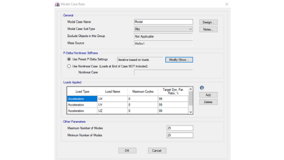 Figure 2: ETABS 2016 Modal Case Data
The 90% of participating mass of the structure can be verified after the model has been completed the analysis. To confirm if we utilize at least the 90% go to Display>Show Table> +Analysis +Results > tick the Participating Mass Ratios and its table will appear on the bottom part of the ETABS interface as shown below. To extract the table, right-click in one of the rows and select export to excel to expand the table.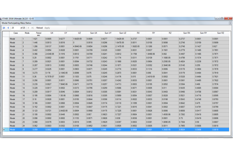
Figure 3: Modal Participating Mass Ratios
It is noticed in Figure 3 above that under the column SumUX, Sum UY and SumUZ reached and exceeded the 90% limit after the 25 number of modes. That satisfies our code requirements!
After the above checklists have been cleared, then we are good to go. The designer should review the structural arrangement of the elements to ensure the code requirements against building irregularity have been satisfied. This includes separate checks for torsional irregularity, review of base shear, drift checks and overall review of the dynamic characteristics of the model. Design and check functions for input appropriate column and wall reinforcement and run check functions to ensure all elements are passing, other independent checks may be completed by the designer but this is primarily for local authority review. These dynamics checklists have been further explained in the succeeding article. So, stay tuned by subscribing and following us on our social media pages for you to be updated with our latest posts!
What about you? Do you have any post-analysis checks in ETABS that can be included and we may miss in the lists above? We’d love to hear from you! Please leave a message on the comment section below. If you find this article helpful and interesting, please share this article and follow us on our social media pages by pressing the icons below. Cheers!
[DISPLAY_ACURAX_ICONS]


For post analysis seismic check you can also add
Torsional irregularity check
Drift check
Soft and Weak story check
Strong column weak beam check
That is right Zain, we can also do that. Usually, those checks that you mentioned are actually right after the post-analysis checks. Once we ensure that the model is geometrically and analytically sound then we can go right away and do those checks before the design process. We will be posting a separate article concerning those checks soon. Stay tuned!
I have a question regarding the modal mass participating ratios. For example, in the results that we obtained above, we see that in the first mode, we have 62.77% of mass participating in translation along Y direction (UY). But we also have 27.37% of mass participating in rotation (RX). So, we see that even for the first mode, we have some torsion associated with it although the primary displacement of the building will be translation in Y direction. Is this amount of torsion acceptable. Do we have any codal provision for that??
Dear All
Please, is it possible to define and assign in Etabs; two different mass sources for each floor?
MSR1 = D1 + M1 x L1
MSR2 = D2 + M2 x L2
In which
MSR1, MSR2 : mass source for floor 1 and 2
D1, D2 : Dead load of floor 1 and 2
L1, L2 : Live load of floor 1 and 2
M1, M2 : Multiplier coefficient of floor 1 and 2.
Best regards