This article outlines the method statement of the construction of Bored Piles which include the general guidelines, the scope of works, working platform, and the construction methodology in the installation of bored piles in a given project. The technical details stated below is still to be verified according to the approved specifications.
1. General
This method statement describes the procedure, the construction procedure, the materials and equipment required for the construction of bored – piles. The intention of the method statement is to give a general guideline for the construction work. Details of the procedures contained herein may be modified based upon actual site requirement.
2. Scope of Work
- 1 No. of working pile load test to 1.5 times the working load.
- Working load is (state the pile capacity as per soil report in KN) for _ Nos. of (pile diameter) mm diameter in working bored piles.
- All Piles shall be integrity tested.
- Production rate will be estimated around (specify no. of piles) piles per day.
3. Working Platform
- The piling work will be carried out from the working platform level.
- The working platform will be made with suitable material by the Main Contractor for the movement of equipment & ready-mix trucks.
4. Construction Procedure
The procedure for the construction of approval of bored piles, with temporary casing under Bentonite slurry system, comprises the following elements:
A. Setting up the Pile position.
B. Installation of temporary guide casing.
C. Drilling of the pile borehole.
D. Recycling.
E. Reinforcement cages in the stallion.
F. Concreting.
G. Removal of temporary guide casing.
A. Setting out of Pile Position
- A qualified full-time surveyor from the Main Contractor will be engaged for setting out of the pile positions using the coordinate system.
- The pile points will be marked by fixing steel pegs in the working platform. After checking the pegs will be driven into the ground to protect them from any disturbance.
- Any pile points, which is disturbed by machinery movement, soil movement etc. will be reset.
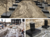
B. Installation Of Temporary Guide Casing
- A Temporary guide casing having an internal diameter same as pile diameter shall be installed to the pile center as previously marked on the working platform.
- The temporary guide casing shall be uniform section throughout the length.
- The casing shall consist of a series of lengths, which will be joined together to extend the length if necessary.
- The verticality of the steel casing is checked with a spirit level in two perpendicular directions.
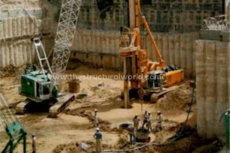
C. Drilling of Pile Borehole
- After the installation of the temporary casing, the borehole will be drilled using appropriate drilling tools. The borehole will be drilled under Bentonite slurry support for the borehole stabilization.
- The drilling fluid is prepared in mixers and kept in tanks for storage and hydration purpose.
- After fixing of the guide casing, the borehole will be drilled down to its final level by means of bucket and auger.
- The Drilled borehole will be filled with Bentonite slurry and the slurry level maintained at the working platform level at all times. In case of any rapid loss of drilling fluid, the borehole will be backfilled without delay using the drilled material from heap near the borehole.
- When the designed depth has been reached which approved by the consultant, the base of the borehole will be cleaned with a cleaning bucket.
- Control tests will be performed on the Bentonite suspension as per specification using a suitable apparatus.
- A sample of the Bentonite suspension will be taken from the base of the boring using an approved sampling device.
- Flushing of borehole will be carried out by using 220mm diameter tremie pipe connected to the mud pump. The fresh Bentonite will be pumped to the bottom of the borehole, where another pump will be used to discharge the overflow Bentonite to the desanding plant.
- When flushing completed another sample of the Bentonite suspension will be taken from the base of the boring. The gravity of the suspension should not exceed 1.25.
D. Recycling
The process of cleaning Bentonite from sand & silt to keep its quality within the allowable limits is called Recycling.
- Recycling will be performed after boring has been completed and the Bentonite has been replaced by concrete.
- The Bentonite from the borehole will be pumped to the desanding plant during concreting.
- After that, the Bentonite will be pumped to the tanks for further use.
Bentonite slurry will have the following properties:
| Bentonite Slurry Properties | Supply to Pile Borehole | Sample from Pile Bore hole |
|---|---|---|
| Density | 1.03-1.10 g/cm3 | 1.02-1.10 g/cm3 |
| Viscosity | 30-90 Sec. | 30-90 Sec. |
| PH Value | 9.5-12 | 9.5-12 |
| Shear Strength | 1.4 -10 N/mm2 | 1.4 -10 N/mm2 |
| Sand Content | Less than 2% | Less than 2% |
In order to achieve a concentration of 5%, 50 kg of Bentonite will be added to approx.1000 liters of water. Mixing will take place in a mixing plant. The Bentonite shall rest in the tanks for at least 4 hours to allow the proper hydration.
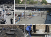
E. Reinforcement Cages Installation
FABRICATION OF STEEL CAGE. Prior to the installation, steel cage will be pre-fabricated at the bending yard by skilled bar bender as per approved design & drawings. After the fabrication has been completed, the steel cages will be linked using D-Shackles at the top and bottom of the steel cage. Hanging supports will be provided to the main reinforcement at the top of the cage to facilitate lifting using the same method.
LOWERING OF THE REINFORCEMENT CAGE. Prior to the placing of concrete, the borehole depth will be checked. The approved reinforcement cage will be lowered into the borehole to the correct level by means of a service crane. The site datum level will be given to ensure the correct positioning of the cage in respect to the cut off level. Correct positioning of the cage within the borehole will be ensured by the use of a Concrete spacer as per approved sample, properly provided to achieve concrete cover of 100mm during concreting. To keep the steel cage in place and at the correct levels, the cage will be hanged to the temporary casing until the concreting is finished.
CONCRETE PLACEMENT. For Concreting operation, separate Tremie pipe sections of diameter 220mm will be joined and lowered, one by one into the borehole until the end of the pipe just contacts the bottom of the borehole. The tremie pipe will then be raised up by 150mm to facilitate the flow of concrete.
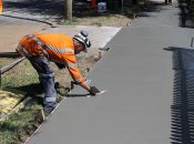
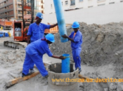
F. Concreting
The concrete is delivered to site by means of truck mixers. The concrete will be checked for the slump and temperature. Cubes will be taken as per specification. The concrete will be allowed to the site only after concrete quality has been found in compliance with specifications.The concrete shall be poured by using concrete pump connected to the Tremie pipe by 90 degrees L-bow without interruption to prevent hardening of the previously placed batch. The Tremie is made up of sections with sufficient length to reach the toe of the pile and the joints provided with seals. The Tremie pipe will be inserted at the center of the pile to reach up to the toe. The Tremie will be lifted 100mm above pile toe level prior to concreting. While concreting the length of the Tremie pipe will be shortened if necessary, however, the Tremie pipe will be maintained full time into the concrete of at least 2.0m length. During the concreting, the level of the concrete will be monitored by use of an end weight tape measure. A sufficient quantity of concrete will be maintained within the Tremie to ensure that the pressure from it exceeds that from the Bentonite slurry. The concrete will be brought up to the working level at least 1.0m above the cut-off level to ensure good quality and contamination free concrete at pile cut-off level. The Bentonite slurry displaced by the concrete will be pumped back to the desander. The concrete above cut-off level will be chipped by the Main Contractor.
G. Extraction of Temporary Casing
On completion of the concreting operation, the temporary casing will be withdrawn by piling rig. When the casing will be extracted, a sufficient quantity of concrete will be maintained within it to ensure that pressure from external water, Bentonite slurry or soil is exceeded and that the pile is neither reduced in section nor contaminated.
We’d love to hear from you, feel free to leave your comment below. Subscribe to our newsletter and follow us on our social media pages.
[DISPLAY_ACURAX_ICONS]
when is the right time to extract the casing? as soon as the concrete pouring is done or do we need to wait for hours before extraction?