web analytics

Method Statement for Dewatering Works


Dewatering System

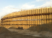
Dewatering works are required in the project locations when the groundwater table was encountered higher than the formation level or the final excavation level. This is to ensure a dry excavation during the foundation works. This is to literally drive away the water from the site during the construction. An example of Dewatering Layout and Details have been provided below for your reference.

Prior to execution, a Method Statement is required to be submitted by the dewatering contractor for consultant approval. Method Statement has been discussed are follows:

1. Purpose

1.1 The purpose of this method statement is to describe the required standards and performance criteria to be used in the execution of dewatering works.

1.2 The purpose of dewatering is to provide a safe, stable, dry working environment in the excavation of (Project Description) with groundwater levels lowered to 1m below the final excavation level.

2. Scope of Works

2.1 The main contract works involve dewatering for the construction of (Project Description and Location).

2.2 To provide a safe, stable, and dry working environment inside the Project using perimeter deep well system.

2.3 The works covered in this method statement has been summarized as follows:

        • Procedure for rotary drilling for dewatering wells and piezometers
        • Procedure for Rotary drilling with Mud Flush
        • Procedure for Rotary Drilling with Air Foam/Mist
        • Installation, Testing, and Commissioning
        • Operation of the Dewatering System
        • Monitoring of Water Levels in the Standpipe Piezometers, and Measurement of Flow

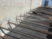
3. Ground Conditions

The site investigation information should be provided and to be indicated in this section.

4. Method Statements

4.1.1 Contractor is to carry out site preparation works: ensure that each location is free of buried services; set out the location of the well; provide suitable, clear, firm, and unobstructed drive-on access for wheeled vehicles with adequate headroom for the drilling rig (25m); provide and a flat stable area (5m x 14m) at each well location.

4.1.2 Well locations shall be marked by the main contractor as approved by the Project Managers. After verifying that the marked well location is safe to drill, and a permit to drill is issued from the main contractor, the drilling rig will be located over the well location.

Dewatering Layout in Progress

4.1.3 Depending on ground conditions encountered, rotary drilling will be carried out with a mud flush and/or an air foam/mist. Both methods are suitable and feasible for drilling in the anticipated strata, but offer different advantages to dealing with formation related issues such as flush loss, or heavy water strikes. The preferred starting method for drilling is air foam/mist; however, conditions in a given borehole such as loss of flush or excessive water may require a change to mud flush. Change of drilling method requires a change of equipment only and does not require any flushing of drilling fluid.

4.2.1 A series of temporary pits approximately 1.5m by 1.5m wide and 1m deep will be excavated at each well location and filled with water. Powdered polymer is added to create a viscous mud. Mud pits will have appropriate edge protection, and be backfilled following drilling.

4.2.2 The guar gum polymer used in rotary drilling has little or no environmental impact and does not pose a risk to the aquatic environment. Therefore, the temporary mud pits will not be lined and will be backfilled with dry material after drilling is completed.

4.2.3 The mud will be pumped through the drilling rods to the bottom of the borehole during drilling. The viscous mud allows for borehole spoils to rise to the surface while also preventing borehole collapse. Upon returning to the ground surface, spoil-laden mud will pass through the mud pit and the majority of the solids will settle out prior to mud recirculation. Settlement of solids will be checked by manual probing of the mud pit.

Mud quality is monitored and evaluated visually by a trained driller. Borehole arising will be checked using a sieve to screen for solids as they exit the borehole to determine ground composition. The mud’s density and viscosity can be altered by adding clean water or additional polymer – this is at the discretion of the driller. If conditions indicate borehole collapse, a temporary steel casing can be used, but only through the superficial soils.

Deep Well Drilling and Installation

Air foam/mist flushing will be used as an initial drilling method, but can also be reverted to in the event of water loss when using mud flush. There is no requirement to remove the mud flush drilling fluid before using air foam/mist.

4.3.1 A compressor is attached to the foam device and drilling rig. The compressor will force air, foam, and water mist down the drill pipes and operate the down-hole hammer when this tool is being used.

4.3.2 Foam is mixed with plain water and injected into the airline by means of a mist pump. This creates a mixture of approximately 90% compressed air to 10% water/foam mixture, however precise measurements are not required. The high pressure and reactions downhole forces the foam into a lattice-type matrix.

4.3.3 Down-hole hammers, powered by compressed air, break soils from the bottom of the borehole and return them to the surface with the assistance of the foam matrix. The arising is monitored visually by the driller to give an indication of the strata encountered, as well as clearly defined water strikes.

4.4.1 Installation of Well Screen

The 6m by 150mm diameter PVC well screens with will be installed in the borehole. Each length will be lifted to vertical using the drilling rig winch and the ends will be joined using threaded ends.  The well screen has a threaded end cap at the base.

PVC Well Screens Installed in the Borehole

4.4.2 Installation of Filter Material

3mm to 6mm crushed gravel will be installed around the liner up to ground level. A suspended weight will be used to check for uniform application and avoid bridging.

4.4.3 Well Development using an Air Lift

    • The end of a weighted air hose will be lowered to about 1m above the base of the well.
    • Air will be pumped from a 250cfm or similar compressor through the air hose. The rising air will create a vacuum in the well which will draw drilling mud and fines through the well screen. The rising air/water mixture will remove these solids from the well.
    • Development will continue until the discharge water is visually free of suspended solids.
READ ALSO:   Methods of Non Destructive Testing in Concrete- NDT

4.4.4 Installation of Pumping Equipment

    • A pump will be prepared with 35m to 40m of drop cable and support rope. The 50mmID risers will be placed next to the well.
    • The support rope will be fitted to the pump and the pump will be placed vertically in the top of the well. The first riser will be connected to the top of the pump.
    • The pump will be lowered and subsequent sections of the riser will be added, continuing until the pump at the desired level. The pump will be suspended by fixing the support rope to the top of the well casing.
    • A half-inch diameter tube will be inserted to within 3m of the base of the well and will act as a conduit for the electronic water meter.

Crushed Gravel Around Deep Well

4.5.1 A 6” diameter, 6-10 bar, High-Density Polyethylene (HDPE) pipe will be used for the discharge header main. The route of the pipeline will follow the perimeter of the excavation and will be coordinated with all contractors on site in order to avoid conflicts of access. Wells will be connected to this discharge line by a flexible rubber hose and control valves.

4.5.2 Procedure for Welding of HDPE Pipes

  • The pipes will be joined using an HDPE welding machine designed specifically for HDPE pipe joining. The welding machine consists of two clamps, a heating plate, and a trimming plate. The clamps are mounted on a skid with one connected to a hydraulic control and one stationary. The heating plate consists of a circular hotplate with temperature gauge. The trimming plate is a rotating circular plate fitted with a trimming blade and is fitted with a purpose-built motor.
  •  The pipes are welded from fixed stations. The pipes will be set at each station and checked for damage. Damaged sections of pipe will be removed by hand saw and discarded. The ends of the pipes should be cut squarely to allow for the flush join.
  • One pipe end is fitted into the stationary clamp and another to the mobile clamp. The pipes will be checked for alignment by touching the two ends. Adjustments to the clamps will be made until the pipes are aligned.
  • The pipes will be separated and the trimming plate fitted between the pipes on the rails of the skid. The trimming plate removes rough and uneven edges from the two pipes by scraping at the pipe walls as the blade rotates over them. This will ensure a proper fit between the pipes. After trimming, the plate is removed and alignment rechecked as described above.
  • The heating plate is placed on the rails of the skid between the two pipes and the pipes are pressed against it using the hydraulic controls. The heating plate melts the ends of the pipes and will require between 45secs and 60secs forming the seal. Once the ends of the pipes show approximately 5mm of melted plastic, the hotplate is removed and the ends of the pipes are pressed together. The fused pipes will be allowed to set for a further 60secs before the clamps are removed.
  • The resulting pipe is pulled forward and another pipe is joined repeating the procedure above. Fittings such as tees or bends are joined by following the procedure above.

4.5.3 Procedure for Installation of HDPE saddles

After laying the HDPE pipes, connection points shall be installed adjacent to the deep wells. A two-inch hole is to be drilled into the top of the header-main and a specially-designed saddle clamp will be fitted around the pipe. The saddle clamp has a two-inch BSP-thread connection that fits directly over the hole in the header-main. The O-rings will be checked prior to installation, and all bolts will be tightened using a hand wrench.

4.5.4 Procedure for Connection of Well to Header main

The installed riser at each pump will be connected to the header main by a flexible armored rubber hose and valves. The saddle clamp will be fitted with a ball valve to control the flow to or from the header-main. Next, a non-return valve (NRV) will be installed to prevent unwanted backflow in the event of pump failure (the direction of the NRV will be checked). A flexible rubber hose will be connected to the well headworks and the NRV by hose connectors and clamps.

Installed Deep Well

  • Two control cabins will be used for the dewatering system. Refer to the attached illustration drawings for the proposed location of the cabins. The control cabin will house the Automatic Transfer Switch (ATS), Electronic Alarm Unit (EAU), control panels, and distribution boards for all dewatering pumps. The cabin will be placed at the agreed location using a crane. The control cabin will be secured with a padlock to prevent unauthorized access.
  • Duty and a standby generator will be connected to the control cabin via the automatic transfer switch. In the event of duty generator power failure, the standby generator will automatically start, ensuring continuous power supply to the dewatering system. The generators will be placed on drip trays to trap any spills or leaks. The trays will be cleaned regularly and hazardous wastes will be disposed of following the site’s hazardous waste policy.
  • A minimum 2m copper earthing rod will be installed near the cabin and tested to ensure that the electrical system is earthed.
  • A qualified electrician will test control panels for correct voltage. The electrician will also check timers and thermal overload sensor settings and function.

4.6.1 Procedure for Installation of Power Cables

    • Steel-wire armored power cables will connect the control cabins to the isolator panels located at each well location. The cables will be laid along the discharge pipeline. The cables will be pulled individually by hand from a cable drum placed on a stand. Ducts will be used for road crossings and pedestrian access points. The cables will be labeled with respect to their well number.
    • A qualified electrician will fix an industrial plug (4pin 3P 440V 16amp, IP 65) to the end of each cable at the cabin. A qualified electrician will fix the end of the cable near the well to an isolator switch (4pin, 3P 440V IP 65). The isolator switch will be mounted to a suitable surface (e.g. steel rebar, wooden stake) between 1m and 3m from the well. The plugs and switches will be checked by multi-meter prior to use.
READ ALSO:   Method Statement for Post-Fixed Rebar

  • The water level in the pumped wells will be measured and recorded using the electronic water level measuring device prior to well commissioning. All water levels will be measured inside the half-inch tube and recorded as “meters below the top of pipe”. This level will serve as an initial water level.
  • The pump will be switched on with the 2” hose disconnected. This will serve as a visual check of the pump's rotation. The water should be discharged at a volume consistent with the capacity of the pump. If the performance is in question, an Electrical Phase Reverser can be used to reverse the direction of the pump and the flow can be checked again.
  • After the rotation of pumps is checked, they can be connected to the header-main. One pump will be operated to pressurize the discharge line. The system will be visually checked for leaks.

4.7.1 Operation, Maintenance, and Risk Management

  • Operation

The purpose of dewatering is to provide a safe, stable, dry working environment in the excavations with groundwater levels lowered to 1m below the final excavation level.

The groundwater level and rate of the drawdown will be monitored using standpipe piezometers.

  • General Operation and Maintenance

The site will be kept neat and tidy at all times; materials will be kept in a designated laydown, area and the area around the wells and header main will be kept free of extraneous items.

Once the system is operational, an experienced dewatering staff will monitor and maintain the system. The planned maintenance schedule for the dewatering system should be maintained.

  • Operation and Maintenance of Control Cabins

During operation, the control cabins will be locked to prevent unauthorized access. The cabins are fitted with an air conditioner which is to remain running at all times to prevent overheating of electrical devices. The cabins are designed to be maintenance free and should remain closed except for testing, repairs, or modifications.

  • Operation and Maintenance of Discharge Pipeline

During operation, the discharge line will be checked regularly for leaks or damage. Any lay flat hose in use will be checked for folds and creases that may restrict the flow of water. The water level in the discharge tank will be checked daily to prevent overflowing.

  • System Risk Assessment

A system risk assessment is provided. The risk assessment is used to highlight the risks to personnel and construction processes for all activities that could be foreseeably hazardous, and to allow for a planned approach to avoiding the hazards, or minimizing their likelihood or severity.

  • Protection Measures

Awareness of the critical nature of the dewatering system is the most important safety measure that can be taken. All site operatives should be aware of the dewatering system’s location and impact that damage to it may have.

The main physical protection measures involve locating the system away from the heavy plant and material movements where possible, and ensuring that only planned crossing routes for haul roads and lifting operations with appropriate protection measures are used. Additional protection measures built into the system should be described.

  • Alarm System

Each control cabin has an electronic alarm unit (EAU) which is activated by any dewatering system failure resulting from electrical malfunction or power loss. The EAU will trigger an audio/visual alarm, and send an SMS alert message to nominated phone numbers.

The alarm will not sound for issues regarding the discharge line. In these cases, site staff will notify WJ via the emergency number. The following sequence should be followed for such events.

  • Isolation of uncontrolled discharge by the closing of valves. Ensure all pumps in the isolated area have been switched off. Return unaffected portions of dewatering system to operation.
  • Implement necessary repairs to allow the full system to be restarted as soon as possible. Implement targeted piezometer monitoring to investigate areas where there is a concern for the sudden rise in groundwater levels.

Deep wells

Water levels in the dewatering wells will be measured by lowering an electric water level sensor into the half-inch dip tube. The water level will be read from the top of the dip tube. The dip tube prevents inflow from giving a false reading of the internal water level.

Standpipe Piezometers

Drawdown between pumped wells will be monitored using standpipe piezometers. Water levels in the standpipe piezometers will be measured by lowering an electric water level sensor into the well casing. The water level will be recorded from the top of the pipe.

Piezometers will be monitored daily by manual dipping. Water levels will be recorded and post-processed to convert to m DMD levels.

Discharge Flow

The discharge flow from the system will be monitored using weir tanks at the discharge point. The v-notch tanks will be positioned on level ground to achieve precise readings of flow.

The flow is recorded by measuring the height of water passing through the v-notch weir of the tank using a steel rule (with mm graduations). The height of the water is measured using a steel rule to record the distance between the nadir of the v-notch and the water level directly above. The measured length corresponds to a flow, computed using the formula (for 90° weir):

Q=1.4h2.5

Where Q = discharge flow in m3/s, and h = meters of water over the weir

The discharge flow from individual wells will only be monitored if there is concern about the performance or condition of a particular pump installation or part of the system. Flow rates for individual pumps will be checked by disconnecting the pump from the ring main and carrying out a time/volume measurement into a container of known volume.

Government Permits

Permit to discharge extracted groundwater will be secured first before discharging into the specified storm water manhole discharge point.

Decommissioning of the System

Upon the advice of the Engineers, the system will be decommissioned. Prior to decommissioning, the pumps will be turned off, but will not be removed from the wells. Water level recovery will be monitored for an agreed period. Should the rate of water level recovery become a significant risk to the works, the pumps will be turned back on. Otherwise, the pumps will be removed.

  • The pumps are removed manually. The riser pipes and dip tubes are collected and placed in the laydown area. The electrical cables will be disconnected from the control panels, rolled, and placed in the laydown area.
  • Water in the header-main will be drained away from the plot to avoid disrupting other works. The 2” gate valves, NRVs, and saddle clamps are removed from the header-main. The discharge header main shall be cut to 6-meter lengths and stored in the laydown area.
  • The control cabin is decommissioned and the generators are disconnected. The equipment is demobilized from the site using a suitable crane.
  • The Main Contractor will allow for the sealing of the deep wells. The deep wells can be sealed by cement grouting as the pumps are removed. The PVC well casing will be cut down and a sealing mechanism such as a ‘puddle flange’ may be used to seal the well.
READ ALSO:   7 Guidelines in Structural Assessment of Existing Building


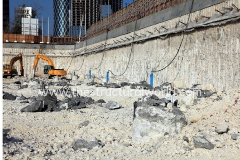
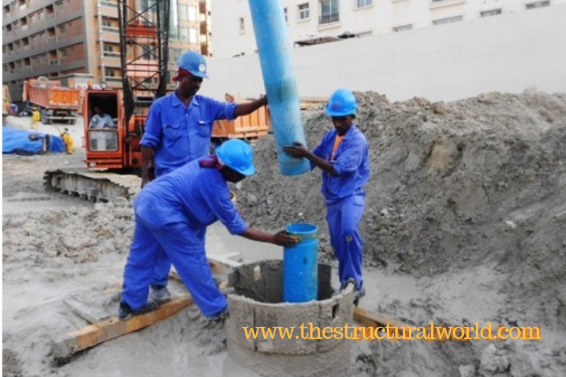
Dewatering in Progress during Excavation

5. Project Organization for Health and Safety Control

The organizational chart should be submitted by the contractor. Templates for the organizational chart is available for download.

5.1 Installation and Commissioning of Dewatering System

An assessment of the risks involved in the installation and commissioning of the dewatering system should be evaluated by the contractor. To evaluate the risk, a health and safety form should be submitted. Refer to the health and safety menu for templates.

5.2 Emergency Action Plan

The action plan shall be implemented at the site in events of emergencies.  The contact numbers of concern personnel shall be printed laminated and shall be posted around the site.

5.3 Risk Management Plan for Dewatering System

This is an assessment of the hazards and probable occurrences that could happen with the dewatering system. Precautionary control measures are also presented to prevent the hazard from occurring; however, action plans or responses together with the timeline for rectifying the problems are also detailed should the hazards occur. The actions and responses can be linked back to the Emergency Action Plan in section 5.2 above.

5.4 Risk Assessment and Management for Damage to Discharge Header main

This is an assessment on the likelihood and impact of a ruptured pipe on the dewatering system and the operations of the project as a whole after taking all precautionary measures specified and consideration of what response procedures are in place.

6. Workplace Access and Egress

6.1 All employees entering the construction area will do so by making use of the access provided. Only authorized employees will be allowed to gain access to the construction site.

6.2 All employees will attend the Project Health and Safety induction prior to entering the area of operation. Access permits will only be issued to employees on completion of the induction.

6.3 Transportation will be provided for workers to and from the site.

7. Workplace Lighting

7.1 Drilling, installation and commissioning works will be conducted during daylight; no work will be conducted after sunset except during emergencies.

7.2 Proper lighting shall be provided when working at night. Tower lights will be operated where required.

8. Plant and Equipment

The following plant and equipment shall be used during the drilling, installation and commissioning stage of the dewatering works

8.1 Drilling Equipment

      • rotary top drive drilling rig mounted on a crawler base (Soilmec 401, 405, or similar)
      • Temporary drilling casings
      • Drilling tools, rods, and bits
      • 4WD vehicle or transit van

8.2 Support Equipment

      • 2” suction pump and hoses
      • mud flush pump and hoses and/or 450cfm/170psi Air Compressor

8.3 Well Installation Materials

      • Filter gravel (crushed limestone 3mm to 6mm)
      • 150 – 200mm uPVC Screen, 0.75mm to 1mm slots, 4m/6m lengths
      • 150 – 200mm uPVC plain casing, 4m/6m lengths

8.4 Development Equipment

      • 250 cfm compressor
      • Weighted air hose

8.5 Installation of HDPE header main

      • HDPE Butt-welding machine
      • Hand saws
      • 6kVA power generator
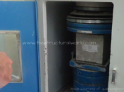
8.6 Operation

      • Power Generators
      • Diesel tank with drip trays
      • Modular Automated Control cabin with control panels and electronic alarm unit

 9. Hazardous Material and Substances

9.1 Diesel fuel shall be used for the drilling rig, and other plant and equipment (e.g. generators, compressor).

9.2 Diesel shall be stored in diesel tanks with appropriate drip trays underneath to catch accidental spills or leaks. Drip trays shall also be placed under any immobile equipment that runs on diesel or petrol.

9.3 Diesel fuel shall be transferred from the tank into the various plant and equipment by a hand pump. Care shall be taken during filling to prevent spills. Temporary drip trays shall be used during filling as required.

10. Waste Management

Waste management will be carried out as per the procedure set out in the project health and safety plan.

11. Special Control Measures

11.1 The safety of all employees shall always be the highest priority during all operations conducted on the project.

11.2 All site operatives and staff working for this project shall attend the Project Safety Induction and the Contracting Company safety induction, prior to working at the site. All operatives will undergo an additional safety induction on the specific hazards of dewatering activities.

11.3 The responsible supervisor will conduct a Safety Task Analysis Risk Reduction Talk (STARRT card) prior to the start of work daily.

11.4 The contractor is committed to ensure minimal risk for its employees and employees of subcontractors and consultants, and to protect the public exposed to construction operations.

11.5 At a minimum, each site operative member will be equipped with PPE such as hard hats, high visibility reflective vest, steel toe cap shoes/boots, coveralls, safety glasses, and gloves.

11.6 When any operation becomes hazardous beyond reason due to unforeseen or uncontrollable circumstances, all affected operations will cease until safe working conditions have been restored. No operation will be considered as too important or urgent as to compromise the health and safety of any employee on site.

When to Shut Off the Dewatering Works

Perhaps the most common questions for engineers is when is the right time to stop or shut off the dewatering works. Dewatering works cannot be stopped until we are sure that is already safe to shut it off. Stopping it means that the water table will come back to its original state. Since the dewatering involves a tremendous amount of water uplift pressure, it is best to calculate whether the weight or mass of the structure is greater than by at least 25% compared to uplift pressure. Refer to Hydrostatic Uplift Check in Basement and Substructure for the detailed calculations.


What do you think about this article? Tell us your thoughts! Leave a comment on the section below. Subscribe to our newsletter to be updated with the latest posts or follow us on our social media pages on the below icons.

Visit Us On FacebookVisit Us On TwitterVisit Us On YoutubeVisit Us On PinterestVisit Us On Linkedin

Loading

Digiprove sealCopyright secured by Digiprove © 2019 The Structural World

Advertisements

Leave a Comment

Your email address will not be published. Required fields are marked *

Verified by MonsterInsights