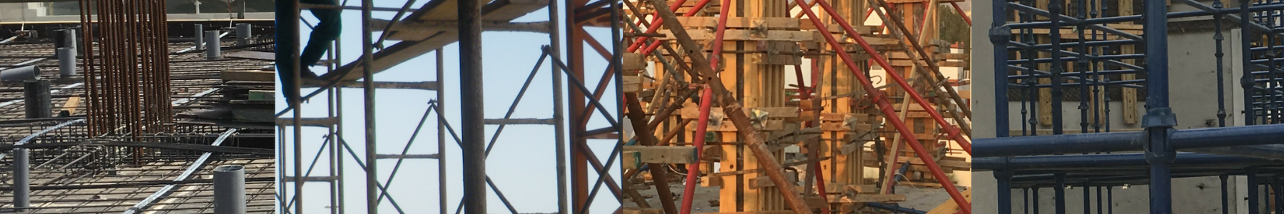
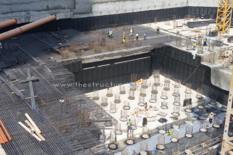
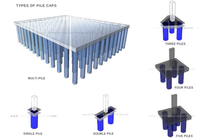
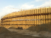
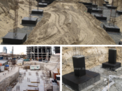
As previously discussed in our article Pile Cap Design Assumptions and Recommendations, Pile Cap is a type of foundation that composed of thick concrete slab built on top of piles used to transmit the load of the structure into the hard strata of the soil. The common types of pile cap use in the construction are differentiated according to the following images:
When to Consider a Pile Cap in Foundation Design?
The considerations of pile cap to use in foundation design were determined through the series of tests and investigations on the soil profile and characteristics from where the project is located. A geotechnical investigation report is then be submitted by the authorized soil laboratory. The allowable bearing capacity usually dictates if a pile cap foundation is required. Though the structural engineer can initially decide if the pile cap is needed at the early stage of design through other considerations as discussed in the previous article, a soil investigation report should confirm otherwise.
Once the soil investigation has been completed, the soil laboratory will confirm and recommend the use of pile caps. Their report will specify the allowable bearing capacity and allowable foundation settlements, allowable capacities under working loads of the recommended diameter of piles, the vertical and lateral pile stiffness or spring constant and the modulus of subgrade reaction. These are the soil parameters needed in pile cap design among others.
Design of Pile Caps in SAFE
The previous article, Top 5 Structural Software That You Should Learn considers SAFE as the most popular tool to design slabs and foundations. Though a lot more software is available out there with the same capacity, let us focus on this sophisticated design tool. How the pile caps can be designed in SAFE? To clearly explain, let us divide it through the guidelines stated below:
1. Column and Wall Load Assignments
We all know that for us to design a foundation, we need column and wall loads from the whole structure to be designed with. Determining the loads that the column and wall will carry under service combination is the preliminary consideration. This can be calculated manually by area method through a column and wall load takedown. But using this method will give us only approximate reactions that we need for foundation design, the lateral forces due to the wind and seismic loadings are most likely will not be captured.
Structural Engineers often uses a 3D analysis model of the proposed project to capture vertical and lateral forces obtained from dynamic analysis. This time ETABS software is capable of doing so. Another way of obtaining the wall and column loads needed in the design is through ETABS export and SAFE import option. To be able to perform this, we need to create first a SAFE f2k file. In this example, it is assumed that we have already an ETABS analyzed model ready. Here is how to do it:
To create SAFE f2k file and to export from ETABS:
In ETABS, Go to File>Export>Story as SAFE V12 f2k file choose “BASE” as Story to Export and tick Loads and Export Floor Loads and Loads from Above. Or get through our YouTube channel for the tip on how to export an ETABS model for foundation modeling and design in SAFE.
To import the created SAFE f2k file:
In SAFE, Go to File>Import> SAFE f2k file>Locate the folder location of the f2k file>Open.

Figure 1.1: Imported Column and Wall Loads from ETABS
Once you completed the export and import option, all the total vertical and horizontal point loads carried by each column and walls generated by ETABS analysis will be imported. The ETABS load combinations will be imported as well. The surface loads such as dead loads and live loads that the pile cap will carry are optional when required.
2. Determine the Type of Pile Cap to Use
The next step to consider is to decide which type of pile cap to use. As a designer, you have the full control and can decide over the best types that are suited according to working loads that each column and walls carry. But, bear in mind that all of your geometric assumptions should have a basis and at least according to codes and standards. Check this link to know more about the pile cap’s code recommendations.
To calculate the required number of piles to be provided in each column and wall, the following formula shall be satisfied:
Number of Piles = Working Load / Pile Capacity
The required number of piles in each column can be designated with reference to the formula above. You can now jot down the numbers of piles accordingly. In this way, you may now have a clearer picture of which type of pile cap to use in your design. Mark the type of pile cap suited in foundation to get ready for the pile cap modeling.
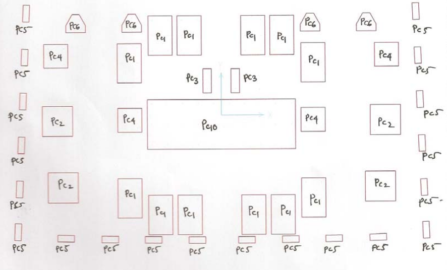 Figure 2.1: Marked Pile Cap Layout
3. Pile Cap Modeling and Design Parameters Assignment
Modeling of pile cap in SAFE is then ready once you completed the designation of which types of pile cap to use in your foundation design. “Save As” the SAFE f2k file generated as previously created to begin the modeling. There are two ways to model the pile cap geometry, either using manual modeling or thru dxf importing. Both of these modeling techniques can be used, but it will take a lot of times doing it manually. So, it is recommended to use the dxf importing to save time and effort in modeling. Check out and subscribe to our YouTube channel on How to Model the Pile Cap in SAFE to Save Your Time, to be published soon.
The load pattern, cases, combinations and material properties as exported from ETABS model has been already included on the imported file, so you don’t need to worry re-defining them. But the slab properties and point spring properties have to be defined to complete the modeling process. Point Springs are the representation of pile support in the pile cap design. Defining the point spring properties has been tackled on our previous article, Pile and Pile Cap Design Considerations.
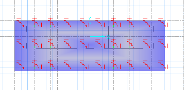 Figure 3.1: Modeled Multi-Pile Pile Cap Showing Assigned Point Springs
4. Run Analysis and Design
Once the pile cap modeling has been completed and the design parameters have been set-up, the next step is to define design strips in x and y directions. Defining design strips is similar to defining design strips in the slab, check this article for guidance. Check the model once more and define the Design Preferences and Design Combos. You are now ready to run the analysis and design. Go to Run>Run Analysis and Design.
5. Review of the Analysis Results
Before the interpretation of the analysis results, take time to review the generated results. Check the punching shear ratio and should be less than unity. For punching shear check design and consideration refer to our previous article. The reaction generated during the analysis should be reviewed and should at least less than the pile capacities recommended by soil report.
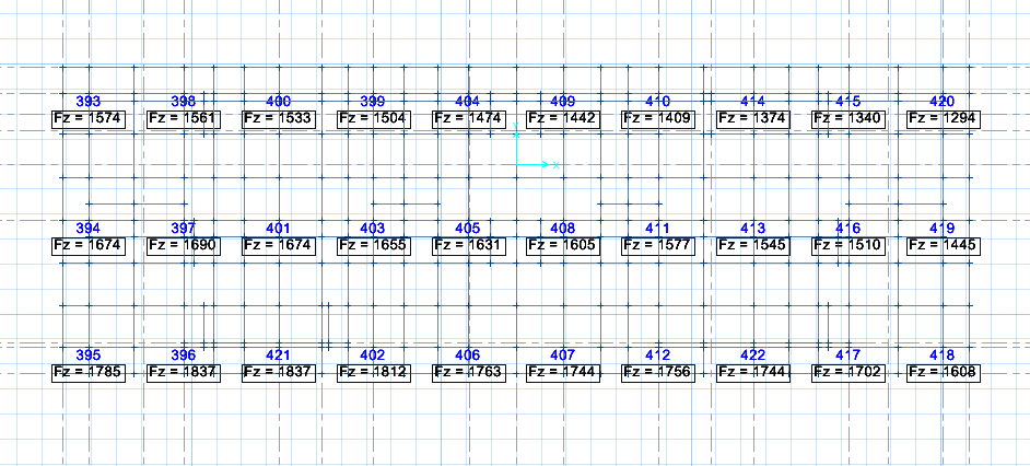 Figure 5.1: Pile Reactions in Pile Cap
6. Interpreting Design Results
Go to Display>Slab Design and set the slab design data accordingly to see the reinforcement results recommended by the software. Here you can play along with the top and bottom mesh reinforcement and that extra top and bottom bars can be interpreted by selecting any of the Reinforcing Display Type at your convenience. You can also view the strip forces when required.
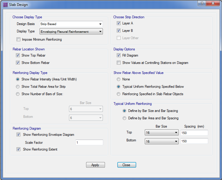 Figure 6.1: Slab Design Window
The slab Strip design as shown in the figure below will be generated upon setting up the slab design. By which the recommended reinforcement by the area of rebar, the total area for design strips and number of bars will appear among the options to interpret.
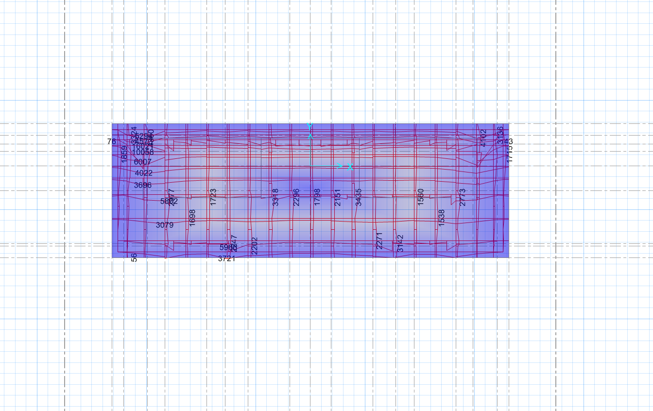
Figure 6.2: Slab Strip Design for X and Y Direction (mm2/m)
What do you think about this article? Tell us your thoughts, leave a message on the comment form below. Leave a comment on the section below. Subscribe to our newsletter to be updated with the latest posts or follow us on our social media pages on the below icons.
[DISPLAY_ACURAX_ICONS]


I found that the strip moment that obtained from strip force was different with design moment used in Slab design. Is it i had made any mistake when drawing the design strip?
Hi admin,
Also, in my case, I am inputting the loading from column manually. My question is that, in case of pile cap modelling. Should i model the loading from column by
1) modelling a column above the pile cap slab and apply point load on the column
OR
2) modelling a slab area (superimposing pile cap slab) and apply surface load on it
Which one do you this is most suitable? And if case 2 is more appropriate, which slab type shall i choose for the column? “Slab” of “Stiff”?