
Long before the birth of sophisticated structural software that aid in design analysis of complex structural elements, the principle design approach is behind in these software developments. Our previous articles-Piles and Pile Cap Design Considerations, Pile Cap Design Assumptions & Recommendation and Punching Shear Checks in Pile Caps merely discuss the design of pile caps using the up to date structural engineering software, the SAFE by CSI. Now, it is time go beyond and understand what’s the basic principle behind the design of pile caps as stated in BS 8110 clause 3.11.4.
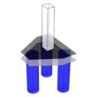
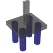
In general, Pile Caps are designed using the principle of bending theory or using the truss analogy. When the truss method is used, the truss should be of triangulated form with a node at the center of the loaded area. The lower nodes are to lie at the intersection of the centerlines of the piles with the tensile reinforcement. Tensile forces in pile caps for some common cases are shown on the figures below.
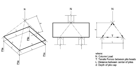 Idealized Truss Pile Cap System
Truss Method
In this principle, if the pile spacing exceeds 3 times the diameter of the pile, only reinforcement within 1.5 times the diameter from the center of the piles should be considered to form a tension member of a truss.
Shear Forces
The shear strength of a pile cap is normally governed by the shear on a vertical section through a full width of the pile cap. The critical section is taken at 20% of the pile diameter inside the face of the Pile. As shown in the figure below. The whole of the force from the piles with centers lying outside this line should be considered.
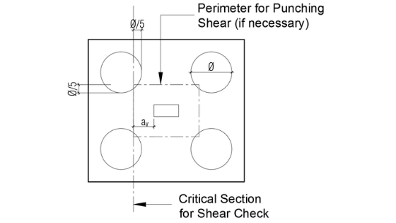
Critical Section for Shear Check in Pile Cap
Design Shear Resistance
The shear check may be made in accordance with provisions for the shear resistance of solid slabs given in BS8110 clauses 3.5.5 and 3.5.6 of the code.
Code Limitations
- The distance av from the face of the column to the critical shear plane is defined in the figure above. The maximum shear stress at the face of the column shall not exceed 0.85 √fcu or 5N/mm2
- If the pile spacing, L is less than or equal to 3 times pile diameter ф, the enhancement can be applied over the whole of a critical section. The enhanced shear stress is 2dvc/av where vc is taken from Table 3.8 of BS8110 or the expression:
where:
(100As/bvd) should not be taken as greater than 3
(400/d)^1/4 should not be taken as greater than 0.67 for members without shear reinforcements and 1 for members with shear reinforcements providing a design shear resistance of ≥ 0.4N/mm2
ϒm=1.25
for fcu > 25N/mm2, above values should be multiplied by (fcu/25)^1/3
- If the spacing is greater than 3 times pile diameter ф, the enhancement can only be applied to strips of width equal to 3 ф on each pile. When enhanced is appropriate, minimum stirrups are not required in pile caps if V < Vc.
- The tension reinforcement should be provided with full anchorage in accordance with section 3.12.8 of BS 8110. The tension bars must be anchored by bending them up the sides of the pile cap.
Punching Shear Checks
To check the punching shear, the following are the design considerations:
- The maximum shear stress at the face of the column shall not exceed 0.85 √fcu or 5N/mm2
- If the spacing of the piles is greater than 3 times the pile diameter, punching shear should be checked in accordance with the figure above, Critical Section for Shear Check in Pile Cap.
A design example of a pile cap will be published soon. So stay tuned by subscribing to our newsletter. Meanwhile, you can avail our spreadsheets for the Design of PILE CAPS for two, three, and four piles. Kindly select the images for more!
PILE CAP Design Spreadsheets
TWO-PILES | THREE-PILES | FOUR PILES |
 |  |  |
What do you think of the above this article? Tell us your thoughts! Leave your message in the comment section below. Feel free to share this article, subscribe to our newsletter and follow us on our social media pages.
[DISPLAY_ACURAX_ICONS]


Is it required to connect the Bottom Reinforcement Pile Cap with Bottom Reinforcement of Raft Slab, although there are Single leg shear stirrup connecting the Bottom pile Cap Reinforcement, with the Top Raft Slab Reinforcements?