External reference or XREF command in AutoCAD is one of the useful features or capabilities of any version of the said drawing software. From the word itself XREF or external reference allows the user to transfer the external reference drawing or images in selected format into the current drawing in order to work from there. This feature is very useful for architects and draftsmen to make the work faster and accurately. This can help and eliminate the redundancy and repetitive task in drafting works since most of the working drawings and plans are made up of typical layout and lines. This may include the grid lines or axis, columns and walls, partition walls, and others. The typical layouts can be attached or laid over on our current drawings without the use of copy-paste commands
But did you know that this AutoCAD capability is also very useful in structural design? How? This command may be familiar for those experienced users of AutoCAD and for newbies who might be their first time knowing about this, here are other learning tips to unlock. This article will tackle how useful is XREF in structural and how to use this command in our daily design works.
1. Creating Framing Plans
We all know that at the start of structural design, we need to create a framing system for the project that we are going to design. A good framing system has to match with the final architectural drawing but not sacrificing the safety and stability of the structure. Some designers tend to print the drawing and put mark-ups from there but it is much easier and economical to do it digitally. Using an AutoCAD’s XREF command helps us to achieve this accurately. To do this, an external reference which is the final architectural plan is needed. Using the XREF command we can overlay the architectural drawing into our proposed framing layout in order to match and coincide with each other without using a copy-paste command. Once overlay we can review if our proposed framing system is coinciding with the architecture especially the slab edges and slab openings.
2. Column Layout
Locating and proposing columns in a proposed project is complicated especially when dealing with complex plans as it involves tremendous coordination with the architectural plans. Thanks to the XREF command, the complexity of this task will lessen. Since most of the layout of the columns is typical, using XREF will help us to review whether our proposed columns are applicable in each floor level. Here we can easily locate those columns that are not matching with architectural walls, door openings, and perimeters edges and easily edit it to coincide with each other.
3. Coordination with other Disciplines
XREF is not only useful in reviewing the architecture with our proposed framing system. It can also useful in MEP drawing coordination, especially when locating the exact position of MEP machines, overhead water tanks, and duct openings. The exact location of the MEP machines is essential for the right design load consideration when dealing with the roof slab design.
4. Review of Shop Drawings
Using XREF is essential when reviewing accurately the related shop drawings and coordination of all the plans and construction layout and drawings. To see whether the overall drawings are matches with each other. This will eliminate the raise of RFI’s or requests for information and possible modification during site construction when the site staff discovers mismatches among each discipline.
How is XREF Command Being Use?
The external reference command or XREF is available in all versions of AutoCAD. We can attach formats such as DWG, Image, DWF, DGN, and PDF. But the very common we are using during the creation of the framing system is using the DWG file. When attaching XREF using DWG as the external reference, both the origin of the reference and current drawing should be at the same point preferably at point 0,0. To locate and check whether both drawings are at point 0,0. Type L>Enter>0,0>Enter and the cursor will go to point 0,0 of the drawing space. Do this in both AutoCAD drawings to confirm that both files had the same origin.
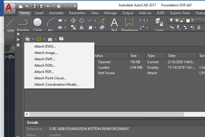
Figure 1: Formats for XREF Attachments
To use the XREF command, type XREF>Enter on your current drawing, and the window similar to figure 1 above will appear. Click the attach icon (document with clip icon) and press Attach DWG when attaching an external drawing and navigate to the file location of the external reference drawing, press the “open” button, and then “ok”. Afterward, you can see that your current drawing has been overlaid with the reference drawing and you can do the check, editing, and draw your proposed framing plan from there easily coordinating with the architectural drawing.
You use the command “REFEDIT” to edit the reference drawing when you need to, turn off the attached external reference, and making the reference file in one layer or color using the “LA” command for you to be able to work on the current drawing easily.
If you want to see more of the above explanation on how to use the XREF command in AutoCAD, kindly watch our video published on our YouTube channel, and subscribe here.
What do you think about this article? We love to hear from you! Leave a message in the comment section below. You can also follow, like, and subscribe to our social media pages below to be updated with the latest posts.
[DISPLAY_ACURAX_ICONS]