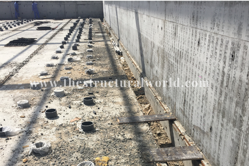
web analytics

Shear Wall Design in ETABS


One of the useful tools in ETABS program is the Shear Wall Design capability. It is not only limited in the analysis of walls but it can also perform the design and check. The designer can be opted to either use the Reinforcement to Designed or Reinforcement to be checked option.  When you require the program to do the design, choose the Designed option and Checked when you let yourself assigned the wall reinforcement to be verified by the program.

In an ETABS analyzed model, the program can perform the following design/check, the procedure in accordance with the specified code requirement:

  • Design and Check of concrete wall piers for flexure
  • Design of concrete wall pier for shear
  • Design of concrete shear wall spandrels for flexure
  • Design of concrete shear walls for shear.

When the pier section is specified to check for the rebar details specified by the designer, the program creates an analysis to determine the flexural demand/capacity ratio, the required area for shear rebar for the selected pier and other output results to determine whether the section is passed or failed.

How to Perform ETABS Design/Check of Shear Wall

In the ETABS analyzed model, go to Design>Shear Wall Design>Assign Pier Sections. Or you can refer to the figure below screenshot from ETABS interface.


Based on the above ETABS figure, the following design options for shear walls are available and can be utilized.

READ ALSO:   ETABS 3 Major Checks Before The Analysis

1. Simplified C & T Design

Referred to as Simplified Compression and Tension this option can only design planar walls and has no option for a checked design. In this option, the pier geometry is defined by the length, thickness, and sizes of each member at each end of the pier.  The pier section flexural design will be performed to edge strip of the wall section and it ignores the resistance from the middle strip.

The program will report the required width of the edge strip to resist the axial and overturning moment required reinforcing in the governing compression and tension load combination. When dealing with shear design the full length of the pier section and reports the required shear reinforcing per unit length. This design option is best to use to determine and design the boundary zones or the boundary elements of shear walls, especially in high seismic areas.

2. Uniform Reinforcing Assignment to Pier

The uniform Reinforcing option is applicable to either design or check both planar walls and coupled shear walls (spandrels). For flexural design or check, the previously defined pier section is automatically picked up by the program and do the design or check. For boundary zones checks and shear design, it analyses the pier sections up into the planar legs and then performs the design and analysis on each leg separately. In this option, the sections assigned as pier will be designed or checked for the uniform reinforcing that the designer assigns.

To do this, the designer should select the pier section or the wall to design and go to Design>Shear Wall Design>Uniform Reinforcing and the figure below will appear. In the following figure, the designer has the option to select which bar size and spacing to provide. You can either tick the Reinforcement to be Checked and Reinforcement to be designed. The reinforcement provided is then verified if passed or failed by going to Display>Show Table>Shear Wall Summary. The interpretation of these results will be further explained in the upcoming articles to be published soon.

READ ALSO:   ETABS Instability Message

Uniform Reinforcing Assignment to Pier

3. General Reinforcing Pier Sections

This section can be defined using the section designer that is built in ETABS wherein the designer can create any geometrical shapes. The designer can also play with the rebar diameters and spacing. The concept of this option is almost similar to the Uniform Reinforcing because the designer has the option to define rebar sizes and spacing. Shear design can be performed similarly with Uniform Reinforcing.

When using the General Reinforcing section go to Design>Shear Wall Design>General Reinforcing and the below figure will appear. The designer can assign which section to assign at the bottom and at the top of the pier with the option to either checked or designed.

ETABS Assign General Reinforcing Pier Sections

Of the three designed/checked options available in ETABS that are mentioned above, the author personally uses the Uniform Reinforcing Options as the most efficient design uses or utilizes all the wall sections not just only end zones. You can always check the end zones of the wall though calculating the boundary zones or boundary elements manually if your engineering judgment told you so. Refer to the video below on how the Uniform Reinforcement option can be done in ETABS. You can subscribe to our channel for more videos like this.


How about you? Which method above did you usually use and why? Tell us your thoughts! Leave a comment on the section below. Subscribe to our newsletter to be updated with the latest posts or follow us on our social media pages on the below icons.

Visit Us On FacebookVisit Us On TwitterVisit Us On YoutubeVisit Us On PinterestVisit Us On Linkedin

Loading

Digiprove sealCopyright secured by Digiprove © 2019 The Structural World

READ ALSO:   7 Dynamic Analysis Checks to Consider in ETABS Model
Advertisements

3 Comments

  1. Andrew

    Hi,
    I’m curious to get your take on Simplified T&C vs uniform reinforcing. Working on a project in a high seismic area, we were getting vertical reinforcing in excess of 1% (requiring lateral ties) when using the uniform reinforcing area for the vast majority of our walls. Using Simplified T&C concentrates the bars in the end zones and then we can provide minimum reinforcing in between the end zone. That said, the length of the end zone is typically about double the required special boundary zone based on the uniform reinforcing method. This means we would need to provide the seismic ties for special BZ for a longer section of wall. Do you have any thoughts on which design method is better in this situation? Our gut is that the T&C method would be better due to the small amount of reinforcing and lack of ties in the middle section of wall but it would be great to be able to combine these methods somehow (without going through the section designer process). Appreciate any input you may have.

    Reply
    1. Q.Y.Mang

      I think: T&C use to shear wall (in planer,for example “I”sharp)is good,not T、L sharp。when I sharp ,calculation like PM,not PMM;when L、T sharp calculation must by PMM modle。
      but,ETABS general reinforceing may be have some bug.In boundary zone,should be use different steel bar diameters,not only edge end —so the reinforcement is arranged in the optimal position and the ansys is also reasonable
      my English so bad。。。。

      Reply
  2. thestructuralworld (Post author)

    In that scenario, I think T&C would have been the better option since your project is located in a high seismic area.

    Reply

Leave a Comment

Your email address will not be published. Required fields are marked *

Verified by MonsterInsights