


Reading structural drawing is a challenge for some who are just starting their Structural Engineering career, as at first glance of it you can see very complicated lines, arrows, and texts. You might feel behind with other Engineers as you don’t really know how to read the structural drawings properly. But in fact, through proper guidance and thorough study reading, structural drawing is just as easy as 1,2,3. Here are the beginner’s guide tricks and tips on How to properly read Structural Drawings.
1. Structural Tagging, Symbols, and Abbreviations.
When dealing with how to read the structural drawing, you will notice symbols and tags in the drawing that you’re not familiar with or not usually encountered, especially if it’s your first time reading and reviewing it. So, it might be helpful to familiarize these symbols when starting to learn how to read a structural drawing. But don’t be worried since most of the tags and symbols found in the structural drawings are usually included in a set of structural drawings, preferably on the cover or first sheet. So if you’re confused about a certain tag or symbol, you can always go back and check this sheet as your reference. Here are the most common symbols and tags that we encountered when reading a structural drawing:
Abbreviations:
C/C: Center to Center
S.S.L: Structural Slab Level
F.F.L: Floor Finish Level
G.L.: Gate Level
NTS: No to scale
SPECS: Specification
U.N.O.: Unless noted otherwise
E.J.: Expansion joint
SCHE. : schedule
T.O.C. : Top of Concrete
RFT/RENF: Reinforcement
TYP: Typical
THK: Thickness
2. General Structural Notes Sheet
A general structural note sheet is usually the first sheet or the cover of the structural drawing. It comprises the summary or the overall construction standards on how a certain project will be executed. It states the compressive or yield strengths of the materials to be used in the construction like the characteristics of concrete, reinforcement bars or the steel required, the standard hooks or bends of rebar, the lap splicing standards, the brief summary of the construction specifications and guidelines to follow during the construction. It also includes the concrete mixtures to be used and the overall workmanship or procedure that the contractor or builder follows. The information on the design criteria and considerations used in the structural design like the load considerations, code standards, soil bearing capacities in foundation design, and a lot more!
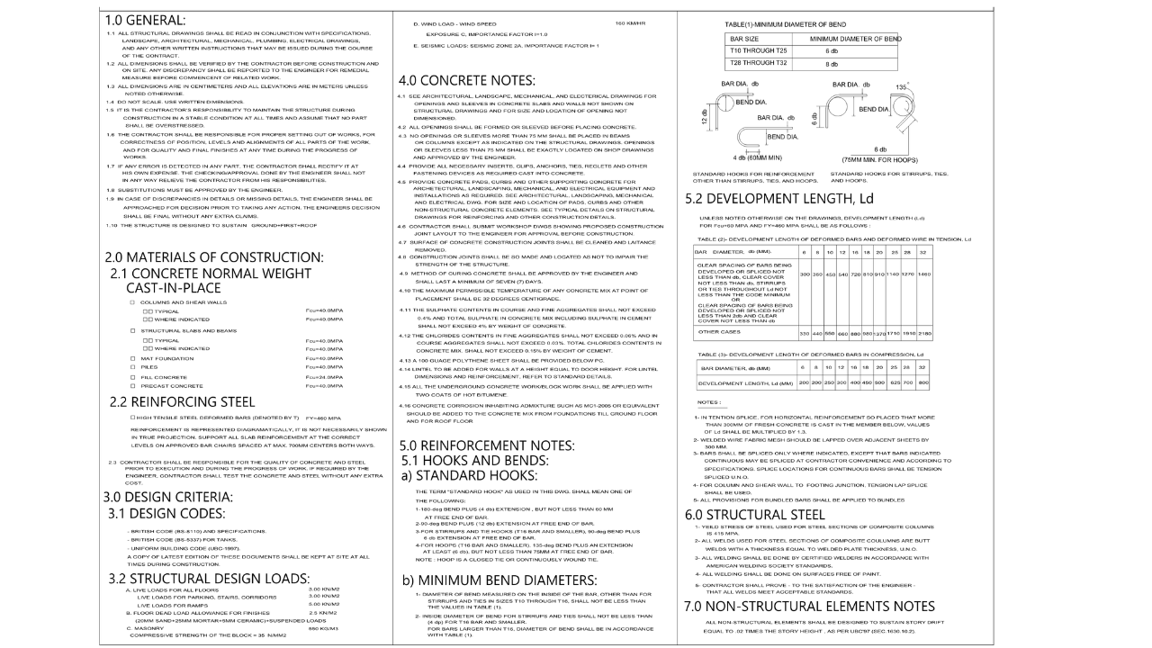
Figure 2.1: Sample of General Structural Details Sheet
3. General Typical Details.
This sheet includes the detailing on the arrangement of reinforcements like the bar bending details in beams and slabs, typical shear wall and retaining wall details and sections, foundations, sump pits, sleeves and slab openings, and column and beams junction details and standard splices. The detailing on the laying of masonry walls and its standard can also be found on this sheet. The good thing about the typical details is that they are self-explanatory and easy to understand.
So if you are struggling and are confused about how each of the structural members will be constructed at the site, you can always check the typical detail sheets to study or review before the site execution.
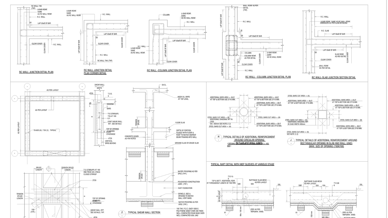
3.1 Sample of Structural Typical Details Sheet
4. Column Layout and Schedule.
The column layout sheet will guide you about the designation of columns and shear walls and locations or dimensions to gridlines. The column layout can be differentiated by the column or wall tags shown on the plan. The schedule sheets of these columns/walls will show the number of rebar and the spacing of stirrups and their reinforcement configurations. This will guide the Engineer to the right information on each of the columns/walls assigned especially during the site works and inspections.
To know the location of column C1 for example, the dimensions from gridlines are indicated and its column tag. To check the number of rebars and spacing of stirrups, you can go to the schedule of the column on the same sheet or a separate sheet in some drawings.
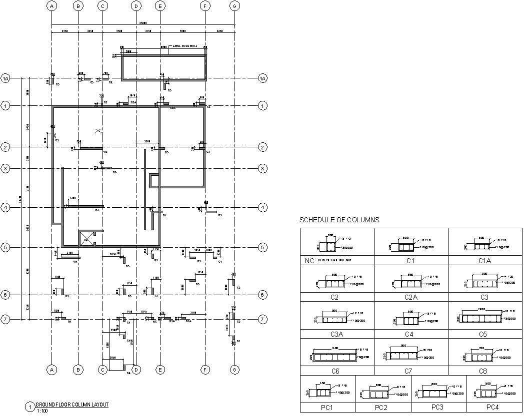
Figure 4.1 Sample Column Layout Sheet
5. Foundation Plan
The Foundation Layout of the project can be found on the foundation plan. In this sheet, you can see the footings to be provided in our project with corresponding foundation tags or labels. Together with the same sheet are the schedule of footing showing the dimension of each footing with thicknesses and schedule of reinforcement for both directions and whether the rebar will be placed on top or bottom of the footing.
The most common type of footing is isolated or combined footing. In some cases, foundations are not limited only to isolated or combined. Especially for bigger projects, we will encounter the types of pile foundations for example. The same as isolated, pile foundation can also be distinguished by tagging the type of pile or pile cap and a corresponding table of schedules will dictate the dimensions, thickness and reinforcement required. Except for those of raft or mat foundation, reading the number of reinforcements and thickness and how it will lay at the site is similar when you are reading a suspended slab which will be discussed shortly.
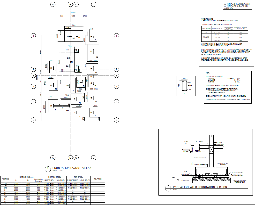
Figure 5.1 Sample Foundation Plan Sheet
6. General Arrangement Plan
The general arrangement plan represents the overall layout in each floor level of the building or the proposed project to be followed in the construction. It contains information about the arrangement or locations of beams and their tags, the type of slabs and their thicknesses, the locations of staircases, lift walls, slab openings, slab depressions, and levels, as well as the section tags and the location of each in the plan, can be found in this layout. G.A. plans are composed of Tie-beam Layout or Ground Floor Framing plan, Typical Floor Framing, and Roof Framing Plans of the project.
When reading, imagine that you are looking at the top of the floor levels it represents. Having the same north direction, all the arrangement and layout you can see when looking from the top is exactly the orientation of it when constructed. It’s like a road map that you need to follow so you will not get lost.
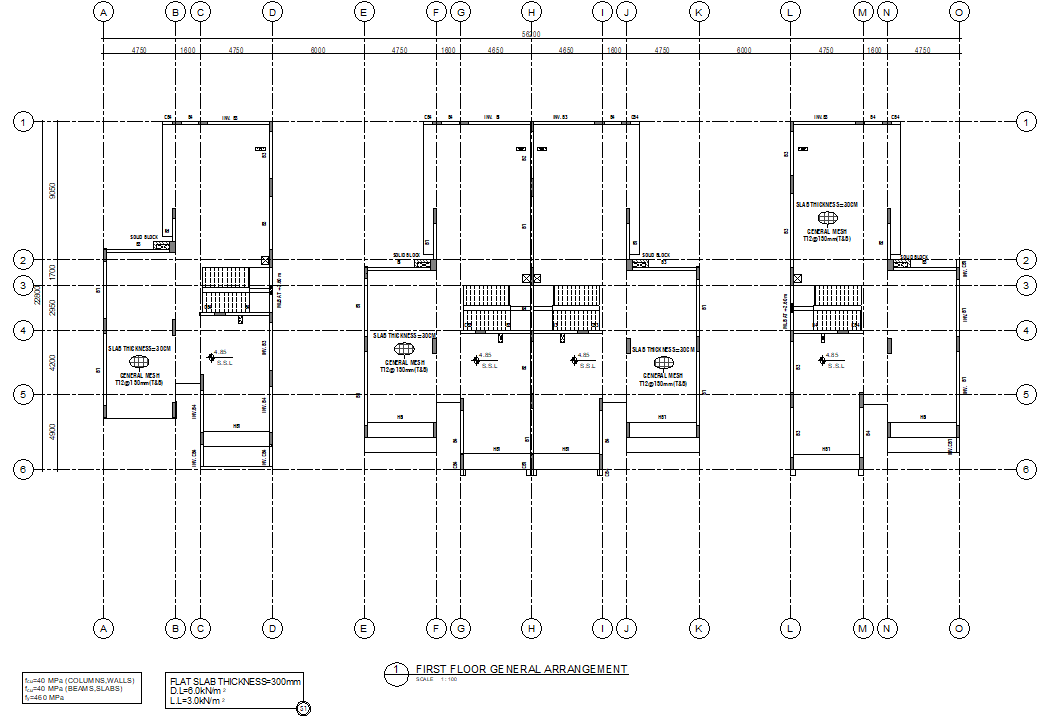
Figure 6.1 Sample General Arrangement Plan Sheet
7. Reinforcement Plan
Reinforcement plans are similar to the general arrangement plans, except that it represents the layout of the overall steel reinforcements that we are going to provide in the floor slab. This is basically a plan which shows a schedule of reinforcement with each corresponding diameter and length and location or position of the reinforcements. When dealing with a concrete slab either one-way or two-way, a schedule of its reinforcement is usually provided in the drawing, and the detail of how the reinforcements are going to be laid, unless noted otherwise, has been shown in the typical detail. When dealing with flat slabs, similar to raft or mat foundations, the drawing is a bit different because the reinforcement arrangements of extra bars whether top or bottom are shown on the plan directly. In this arrangement, you can see the orientation of it and an arrow indicating the directions of laying. The rebar diameter and spacing are also indicated with the schedule of the main mesh reinforcements of the said slab.
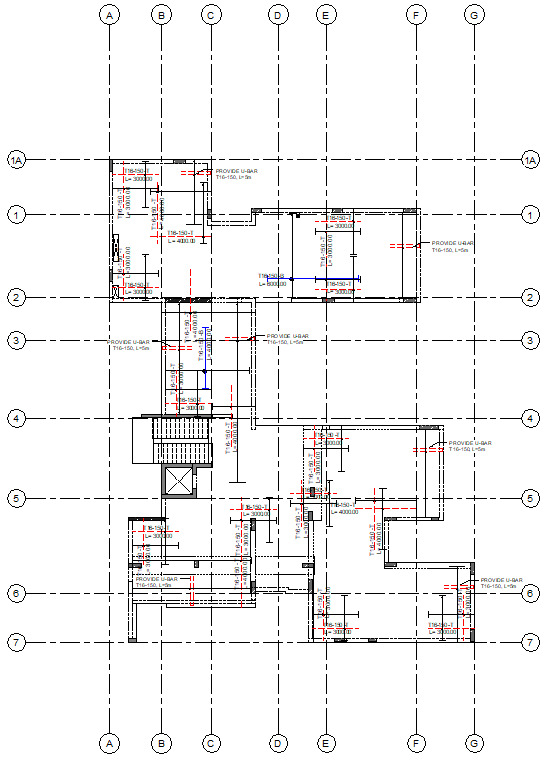
Figure 7.1 Reinforcement Plan Sheet
8. Structural Details/Typical Sections Sheets.
The structural details with reference to the section tags we encountered in the GA plans are usually provided in this sheet. In this drawing, we often see the structural connection details, the slab depression details, drop panel details, parapets, punching shear links, corbels, staircases details, and the actual rebar details in some of the structural members, and the like. The special details that the structural designer wants to show in the drawing can be found here. So if you get lost thinking about how the details would be, which you can’t find in the General Typical Detail sheet, the structural detail sheet would be the right place to check.
9. Boundary Wall Sheets.
Boundary Wall also known as compound wall drawings shows the overall layout considering the perimeter fence along the plot limit. In this sheet, the compound wall’s tie-beam layout, and the compound wall footing are shown as eccentric. The information about the gate level, existing road levels, and whether the plot limits are near existing neighbors or roads are provided, we can also notice if the foundation of the main building/project we are constructing is near the plot limit. The overall footprint or the bird’s eye view of the structure in consideration can be easily tracked when reviewing this sheet.
10. Shoring Layout and Details.
A Shoring Layout sheet can be added depending on the site condition. Shoring layout and Details are provided when we need to support our excavation for the possible collapse of the existing structure nearby. This scenario happens when the difference in levels of the existing gate level is more than 1.20m compared to the lowest natural ground level that occurs along the plot limit. Additionally, when our proposed project has basement levels, shoring work is a must. When reading this sheet, you will be guided on where to provide the shoring works in the plan. Whether soldier piles, secant, or tangent pile shoring, all the section details have been clearly identified and provided here.
What do you think about this article? Are there any tips you can add to the above? Let us know your thoughts and comment down below. You can also follow, like, and subscribe to our social media pages below to be updated with the latest posts.

![]()


Read drawing