


Our previous article, Retaining Wall: A Design Approach discusses the principle and concept behind and when and where to consider a retaining wall in our design. We have learned the different checks against the mode of failures in the retaining wall should be considered in the design. To further understand the designed approach, here is a worked example of the design of the retaining wall.
This example is intended to be readily calculated by hand although a lot of structural spreadsheets and software such as Prokon are available. The purpose of this article is for the reader to fully understand the principle behind it.
Worked Example:
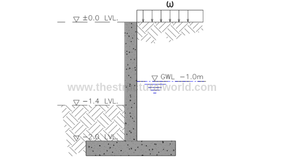
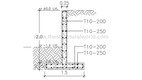
Consider the cantilever retaining wall with the cross-section shown in the above Figure A.1, which retains a 2m depth of soil having the groundwater table at -1.0m level.
Design Parameters:
- Soil Bearing Capacity, qall : 100 kPa
- Coefficient of Soil Friction, ф: 30°
- Unit Weight of Soil, ɣs: 18 kN/m3
- Unit Weight of Water, ɣw: 10 kN/m3
- Unit Weight of Concrete, ɣc: 25 kN/m3
- Surcharge, ω: 12 kN/m2
- Ground Water Level: -1m from 0.00 level
- Height of Surcharge, h: 0.8m
- Height of Wall: 2.0m
- f’c: 32 Mpa
- fy: 460 Mpa
- concrete cover: 75mm
1. Analytical Geometry and Variables
Before we proceed with the design, it is important for the designer to know the geometric variable and parameters of the retaining wall. Refer to Figure A.2 below.
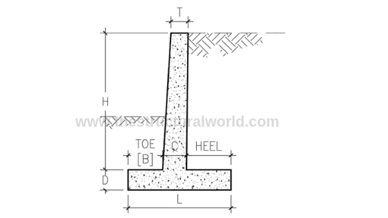
Figure A.2-Retaining Wall Geometric Variables
where:
- H: Height of the retaining wall
- L: Width of the base
- D: Thickness of the base
- B: Width of the toe
- C: Stem thickness at the bottom
- T: Stem thickness at the top
2. Approximate Proportions of a Cantilever Retaining Wall
The next thing to consider is the assumptions that we can make in terms of the geometry of the retaining wall that we are designing. Given the height, H of the retaining wall, we can assume or counter check our initial design considerations should at least according to the following geometric proportions:
- Base width: L= 0.5H to 2/3H
- Thickness of base: D= 0.10H
- Stem thickness at the bottom: C=0.10H
- Width of the toe: B= 0.25L to 0.33L
- Stem thickness at the top: t=250mm (minimum)
Based on the above approximate geometric proportions, let us assumed the following parameters to be used in our design:
- Base width: L= 1.5m
- Base thickness: D= 0.25m
- Stem thickness: C=t =0.25m
- Width of Toe: B= 0.625m
3. Analytical Model
Sketches of the retaining wall forces should be considered to properly distinguish the different forces acting on our retaining wall as tackled in the previous article, Retaining Wall: A Design Approach. Based on our example in Figure A.1, we have the forces due to soil pressure, due to water and surcharge load to consider. Figure A.3 below is most likely our analytical model.
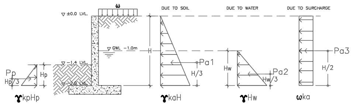
Figure A.3-Retaining Wall Forces Diagram
Considering the Figure A.3, we can derive the following equation for the active pressures, Pa and passive pressure Pp. Notice that the pressures acting on the wall are equivalent to the area (triangle) of the pressure distribution diagram. Hence,
- Pa1=1/2 ɣKaH2 →eq. 1, where H is the height of retained soil
- Pa2=1/2 ɣHw2 →eq.2, where Hw is the height of the groundwater level
- Pa3=ωKah →eq.3, where h is the height of surcharge
The passive pressure, Pp would be:
- Pp=1/2 ɣkpHp2 →eq.4
Values of Coefficient of Pressure, ka and kp
According to Rankine and Coulomb Formula, the following are the equation in calculating the coefficient of pressure:
Ka= (1-sin ф)/(1+sin ф)
Ka= 0.33
Kp= (1+sin ф)/(1-sin ф)
Kp= 3
Substituting the values, we have the following results:
-
- Pa1=1/2 ɣkaH2 = 11.88kN
- Pa2=1/2 ɣHw2= 5kN
- Pa3=ωkah= 3.17 kN
- Pp=1/2 ɣkpHp2= 9.72kN
3. Stability Check:
There are two checks to consider the stability of the retaining wall. One is the check for an overturning moment and the other one is the check for sliding. The weight of the retaining wall including the gravity loads within it plays a vital role in performing the stability check. Refer to Figure A.4 for the mass or weight calculations.
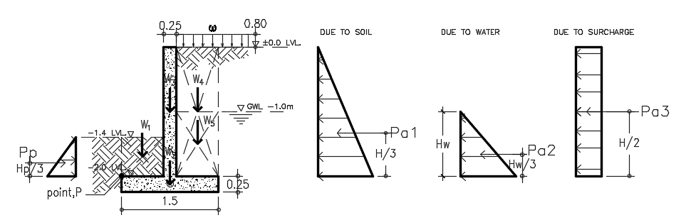
The self-weight component of the retaining wall should be factored down or to be multiplied by weight reduction factor (0.9) to account for uncertainty because they are “stabilizing” in this context. Hence,
-
- Weight due to soil: W1= 18kN/m3 x 0.6m x 0.625m x 1.0m = 6.75kN
- Weight due to footing: W2= 0.9 x 25kN/m3 x 0.25m x 1.5m x 1.0m = 8.44kN
- Weight due to wall: W3= 0.9 x 25kN/m3 x 0.25m x 2.0m x 1.0m = 11.25kN
- Weight due to soil: W4= 18kN/m3 x 0.625m x 2.0m x 1.0m = 22.5kN
- Weight due to water: W5= 10kN/m3 x 0.625m x 1.0m x 1.0m = 6.25kN
- Weight due to surcharge: Ws= 12kN/m2 x 0.625m x 1.0m = 7.5kN
- Total Weight, WT = 62.69kN
3.1 Check for Overturning Moment:
To satisfy the Overturning Moment Stability, the following equation should follow:

where:
-
- RM: Righting Moment due to the weight of the retaining wall
- OM: Overturning Moment due to lateral earth pressure
With reference to Figure A.4 diagram and taking moment at the point, P conservatively neglecting the effect of passive pressure hence:
- RM= W2 (0.75) + W3(0.75) + W4(1.19) + W5(1.19) + Ws(1.19) = 57.91 kNm
- OM= Pa1 (0.67) +Pa2 (0.33) +Pa3 (0.4) = 10.88kNm
RM/OM = 5.32 > 2.0, hence SAFE in Overturning Moment!
3.2 Check for Sliding
To satisfy the stability against sliding, the following equation should govern:

where:
-
- RF: Resisting Force
- SF: Sliding Force
The sliding check should be carried out with reference to the Figure A.4 diagram and considering the summation of vertical forces for resisting force and horizontal forces for sliding force conservatively neglecting the passive pressure, hence:
- RF= W1+W2+W3+W4+W5+ Ws = 55.94kN
- SF= Pa1+Pa2+Pa3 = 20.05kN
RF/SF = 2.79 > 1.5, hence SAFE for Sliding!
4. Check the Wall Thickness for Shear
The nominal shear is equal to the lateral forces on the retaining wall, neglecting the effect of passive pressure which will give us:
- Nominal Shear, Vn = 20.05kN
- Ultimate Shear, Vu = 1.6Vn = 32.08kN
For the thickness of the wall to be safe in shear, the ultimate shear, Vu should less than the allowable shear, Vallow as recommended by the ACI 318 code.

Vc = 0.17√fc’bwd
where: ф=0.75
bw=1000mm
d= 250mm-75mm-6mm = 169mm
Vc = 0.17√fc’bwd = 162.52kN
Vallow= 121.89kN
Since Vu < Vallow, hence SAFE in Shear!
5. Design the Wall Stem for Flexure
- Nominal Moment, Mn = 10.88kNm
- Ultimate Moment, Mu = 1.6Mn = 17.40kNm
Mu =φ fc’ bd2ω (1- 0.59 ω)
17.40×106 = 0.90 x 32 x 1000 x 1692 ω (1-0.59 ω)
ω = 0.0216
ρ = ω fc’/fy= 0.00150
As= ρbd = 0.00150x1000x169 = 254mm2
Asmin= ρminbt = 0.002 x 1000 x 250 = 500mm2
Required Vertical Bar: Try T10-200; As act= 392mm2 x 2 sides = 785.4mm2
Required Horizontal Bar: Try T10-250; As act= 314mm2 x 2 sides= 628.32mm2
Hence: use T10-200 for vertical bar and T10-250 for horizontal bar.
6. Check for Bearing Pressure under Footing
The foundation bearing capacity usually governs the design of the wall. The soil, particularly under the toe of the foundation, is working very hard to resist the vertical bearing loads, sliding shear, and to provide passive resistance to sliding. The bearing capacity of the soil should be calculated taking into account the effect of simultaneous horizontal loads applied to the foundation from the soil pressure.
For the footing to be safe in soil pressure, the maximum soil pressure under working load shall be less than the allowable soil bearing capacity. The maximum soil bearing pressure under the footing considering 1m strip is:

where:
-
- P= 62.69kN
- A= (1×1.5) m2
- M=10.88 kNm
- b= 1m
- d=1.5m
Substituting the values above will give us:
qmax= 70.81kPa < qall=100 kPa, hence, oK!
Solving for Ultimate bearing pressure:

where:
-
- P= 1.6x 6.75 + 1.4×8.44 +1.4×11.25 +1.6x 22.5 +1.6×6.25 +1.6×7.5= 96.37kN
- A= (1×1.5) m2
- M=17.40kNm
- b= 1m
- d=1.5m
Substituting the values above will give us:
- qumax= 110.65kN
- qumin= 17.85kN
7. Check the Required Length of the Base
If qumin is in tension check the required length otherwise ignore if it is in compression. Since our qumin is tension (+), the value of L must be computed as follows:
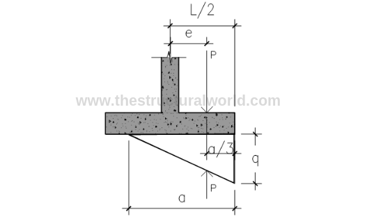
Figure A.5-Pressure Diagram under Tension
From Figure A.5:
Solve for Eccentricity:

e=M/P = 0.181

where:
-
- a=length of pressure
- qe= qumax
- b=1 meter strip

-
- a= 1.74m
L= 2(e+a/3) = 1.52 say 1.6m
8. Check the Adequacy of Footing Thickness for Wide Beam Shear
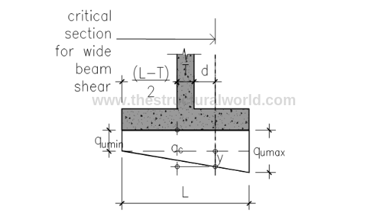
Fig A.6-Pressure Diagram under Compression
8.1 When qumin is in Compression

Solving for y by similar triangle: referring to Figure A.6 above
y/1.044 = (112.24-19.44)/1.5; y = 64.59 kPa
qc= 19.44 + 64.59 = 84.03 kPa

- L’= (1.5m-1.044m) = 0.456m
- B= 1m strip
- qumax=112.24kPa
Vu= 44.75kN
8.2 When qumin is in Tension
qc=y
Solving for y by similar triangle: (referring to Figure A.6 above, L=a=1.75)
y/1.244= 112.24/1.75; y = 79.79 kPa
qc=79.79kPa
Vu= 1/2 (qc + qumax) L’b
- L’= (1.6m-1.244m) = 0.356m
- B= 1m strip
- qumax=112.24 kPa
Vu=34.18kN
Hence, use: Vu=44.75kN
Vallow= фVc
Vc = 0.17√fc’bwd
where:
-
- ф=0.75
- bw=1000mm
- d= 250mm-75mm-6mm = 169mm
Vc = 0.17√fc’bwd = 162.52kN
Vallow= 121.89kN
Since Vu < Vallow, hence SAFE in Shear!
9. Check the Wall Thickness for Flexure
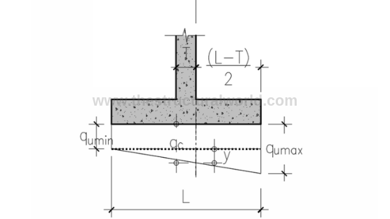
Figure A.7-Pressure Diagram for Flexure Check
9.1 When qumin is in Compression
Solving for y by similar triangle:(referring to Figure A.7 above)
y/0.875 = (112.24-19.44)/1.5; y = 54.13 kPa
qc= 19.44 + 54.13 = 73.57 kPa
Mu= (73.57×0.625) x (0.625/2) + (38.67×0.625) (1/2) x (2/3) (0.625) → (area of trapezoid x lever arm)
Mu=19.40 kNm
9.2 When qumin is in Tension
qc= qumin + y
Solving for y by similar triangle: (referring to Figure A.7 above. L=a=1.75)
y/1.075 = 112.24/1.75; y = 68.95 kPa
qc=19.44 + 68.95= 88.39 kPa
Mu = (88.39×0.75) x (0.75/2) + (23.85×0.75) (1/2) x (2/3) (0.75) → (area of trapezoid x lever arm)
Mu= 19.40kNm
Hence, use Mu=29.33kNm
Mu =φ fc’ bd2ω (1- 0.59 ω)
29.33×106 = 0.90 x 32 x 1000 x 1692 ω (1-0.59 ω)
ω = 0.0364
ρ = ω fc/fy= 0.002532
As= ρbd = 0.002532x1000x169 = 428mm2
Asmin= ρminbt = 0.002 x 1000 x 250 = 500mm2
Required Vertical Bar: Try T10-200; As act= 392mm2 x 2 sides = 785.4mm2
Required Horizontal Bar: Try T10-250; As act= 392mm2 x 2 sides= 628.32mm2
10. Reinforcement Details of Retaining Wall
The presented calculations above are actually too tiring to perform manually especially if you are doing a trial and error design. Thanks to structural design soft wares and spreadsheets, available nowadays, our design life will be easier.
Our team developed a user-friendly spreadsheet for the design of cantilever retaining wall based on the above calculation. Grab your copy here!
What do you think about this article? Tell us your thoughts! Leave a comment on the section below. Subscribe to our newsletter to be updated with the latest posts or follow us on our social media pages on the below icons.

![]()


i need for your help minimum depth for stone masonry wall refer to ACI code is how much?
kindly send me with Ref of ACI code
You can use the parameters written in section 2 of this article and confirm whether the thickness is adequate using a shear check.
This is a helpful guide to Retaining Wall design. However, I have noticed errors in Section 3’s loadings. For example, Pp is not substituted correctly. I have not checked further than this.
It would be worth double-checking the spreadsheet you are selling as this is a dangerous error that would show a retaining wall having a higher capacity than it actually does.
Thanks for pointing out. We have checked and found out that that is merely a typo error and it has been updated accordingly. We have also double-checked the attached spreadsheet and it is not affecting the results as we conservatively neglect the effect of passive pressure in the calculation.
Helpful guide. Which section in ACI360 the calculations are referred to?
Hello
Can you explain why the height of the surcharge is only 0.8m and why is it not reflected on the Analytical model ?
Its very detailed example , thanks for that.
Also ,would you be able to explain how is the d in critical shear calculated ? number 1.044 is used for similar triangles,however I struggle to find exact theory how you arrived to this number as I get different.
Substitute the values from (L-T)/2 + T + d, where L=1.5, T=0.25 and d=.169. That will give us 1.044.
In this example, a 0.80m surcharge height is a given parameter. In the analytical model, the surcharge, ω is mentioned and the height corresponds to that is 0.80 m.
Very helpful information.. thanks for sharing
Thanks Rosina!
where do you get this 1.244 on similar triangles under (qc = y) condition. Thanks in advance!
You need to use effective stress when doing the calculation.
we have to learned the different checks against the mode of failures in the retaining wall should be considered in the design. Here some worked examples of the design of the retaining wall are described.I like the I have also found this resource Rfmasonry.co.nz useful and its related to what you are mentioning.
Could you please clarify why in section 7 you determine L=1.6m, but later in the calculation you still use L=1.5m? thanks a lot.
I find this helpful though.
In the overturning moment, you have this factor: W1 (0.313)
Where do you get the 0.313 from?
PS I purchased the spreadsheet!
why we used 18 kn/m^3 insted of 12 kn/m^3 when we calculate the weight of surcharge?
This is just a typo error and we corrected this according to 12KPa as per the attached spreadsheet.
while calculating restoring moment is it good to take moment due to surcharge load because surcharge load may be transient in some cases , like fire tender or other vehicular load
fine example for design
Why did you put 1/2 for Pa1 instead of 1/3 as it is H/3 with triangular load?
Notice that the pressures acting on the wall are equivalent to the area (triangle) of the pressure distribution diagram. Upon getting the Pressure, we will multiply it by h/3 to get the moment.
What does the height of the surcharge, h, represent? You have given us the value of the surcharge, so I can’t work out what the h is referring to?
I’m amazed at your Math skills! However, retaining walls can also be built through stone masonry construction. But yeah, the cost and quality should be considered.
Hi,
in the section “Check for Sliding”, I think you have forgotten to multiply the vertical weight to “tan(2.fi/3)”. if you do that Rf would be reduced 55.94 x 0.35= 19.50, as a result, the design cannot pass the sliding check.
the active lateral load should be against the passive lateral load, not the vertical load.
Does this spreadsheet allow for an offset footing where the toe length is different than the heel lenth.
Also, why vertical rebar on both faces of the stem? Primary vertical rebar should be on the tension (back/burried) face.
This excel is for retaining walls with concentric walls to its foundation only. Yeah, that’s right theoritically, the primary bar should place on the tension side of the wall only. But, practically speaking, or in actual it’s best for the designer to add another rebar on the other side, just in case.
I bought the file, yet why cant I edit the file so i may be able to put my own logo for the finished output?
Is it not allowed? I mean like I already paid for the file.
Thanks and would really appreciate a feedback on this one.
Hi Ruben, you can actually put your own logo on the space provided. Either editing some option setting on your excel or typing your company name on it. If none of these options are working, do it manually. Once you finish the design, convert the file to pdf and paste your logo from there.
it would have been better, if you can reference the equations.
Hi, thank you for this example. It is really helpful.
I just have a question about the unit weight of soil used. Below the groundwater level, the active earth pressure shouldn’t be calculated considering the submerged unit weight of soil?
IT CAN BE ALLOWED TO USED THE MINIMUM STEEL RATIO OF 1.4/fy ? for vertical reinf of retaining wall.
I think your RM is incorrect in its total value. Each time I calculate it I get 57.91KN, not 60.02KN
Thanks, Aaron for pointing it out. We have checked and found out that that is merely a typo error and it has been updated accordingly. We have also double-checked the attached spreadsheet and it is not affecting the results in the calculation.
Sir, would you please to explain about qumax 112.24 and qumin 19.44 respectively of article 8.1.Thanks.
This sit is very good,how can i become member.
Hi, Thanks for the detailed calculation. How if the surcharge height is not given, what estimation can we use?
is there unit in imperial ? or only in metric
This is in the metric unit. Imperial or SI unit is under development.
Good day
Our lecturer used this exact extract as a curveball to calculate retaining walls with water, I found this before we had to give it in…full marks then :D.
Why do you not use friction forces to calculate FR, FR = ΣV * tan(k1*Φ1) + k2C2B + Pp
There is no cohesion forces hence k2C2B = 0
But the rest will equate to 32.54kN
Then sliding test will be 1.62>1.5 = OK, this is how we are taught.
Could you elaborate on your method for sliding and where the 0.9 safety factor comes from for the concrete weight. I have tried to find this info in our foundations handbook with no success.
I also see your turning point is not at an extreme point. You use the top of your toe instead of the bottom. From what I can see this means your moments won’t be accurate, but it will give similar results.
There is also a comment earlier about a typo of MoT = 57.91, the figure was right at 60.02, the weight of section 1 was not added to the equation. Though all of these moments are taken from the top of the toe and not the furthest point, thus moments are not accurate.
Principle is good, great article.
sir, Thank you for your valuable information. this is very much useful and one more plea that can we have any examples for considering wings & returns with head wall can be treated as a retaining wall any such kind of examples please post to mail if any thanks in advance
Hi
Great example. Thanks. Wouldn’t you think you need to add the vertical stress applied on the wall base due to the surcharge and also calculate its moment?
Thanks
Mike
Thanks, Mike! The surcharge is already considered in the example.
Good day. May I ask if why bw is equal to 1000 mm? As per ACI R11.1:
The shear strength is based on an average shear stress on the full effective cross section (bw x d). In a member without shear reinforcement, shear is assumed to be carried by the
concrete web. In a member with shear reinforcement, a portion of the shear strength is assumed to be provided by the concrete and the remainder by the shear reinforcement.
Thus, the assumed cross section must be 250 mm (base thickness where shear failure is expected) x 169 mm.
Hi, awesome example! I have a question though, in the overtunring moment:
RM= W2 (0.75) + W3(0.75) + W4(1.19) + W5(1.19) + Ws(1.19) = 57.91 kNm
OM= Pa1 (0.67) +Pa2 (0.33) +Pa3 (0.4) = 10.88kNm
where did 0.75, 1.19, 0.67, 0.33 and 0.4 came from? are those USA safety factors or what?
Those are lever arms! With reference to Figure A.4 diagram and taking moment at the point P.
Hey, thanks! I did get now where the
0.67, 0.33 and 0.4 in OM
came from there the height of the resultant,
but I still cant figure out the
0.75 and 1.19 from RM, are they the distance to a certain turning point?
would you please to explain about qumax 112.24 and qumin 19.44 respectively ???
in check the wall thickness for flexure section
Mu= (73.57×0.625) x (0.625/2) + (38.67×0.625) (1/2) x (2/3) (0.625)
How is this calculated
and where did we get 38.67 from
Please explain
Thank for this detailed design to follow; It has been very helpful. One thing I noticed is that the calculation for the wall stem does not match the value you then indicated for the moment when checking for wall stem flexure. You have listed that Mu=19.40KNm again for tension, but the calculation comes out to the 29.33KNm you used. I believe it was just a typo but it made it a bit confusing to follow then. Thanks again, and God bless.
Just an FYI, with water behind the retaining wall, the soil weight should be submerged (subtracting water unit weight from soil) to determine the active pressure. Without water in front of the wall, you’ll also have an uplift force along the underside of the footing due to buoyancy, equal to the depth of water behind the wall at the heel, tapering to the depth of water in front of the wall at the toe.