

Assessing the Torsional Irregularity with the building we are designing can be somewhat confusing, particularly for those new to the process or for those who haven’t done it in a while. However, with the proper guidance on the underlying principles, it becomes much more manageable. If you find yourself forgetting why this check is necessary, it’s advisable to revisit our previous article to refresh your memory before proceeding further.
In this article, we will demonstrate how to conduct the torsional irregularity check using data obtained from ETABS analysis. The steps outlined below are specific to an already analyzed ETABS Model. For this demonstration, we’ll utilize the ETABS 2021 version.
1. Verify if Torsional Irregularity Exist
The initial consideration involves assessing whether the building under design exhibits torsional irregularity. If such irregularity is present, the ratio of maximum drift to average drift exceeds 1.20. To verify this in ETABS model, proceed as follows:
Go to View > Display Table>Analysis Results>Joint Output>Displacements>Story Max Over Avg Drifts
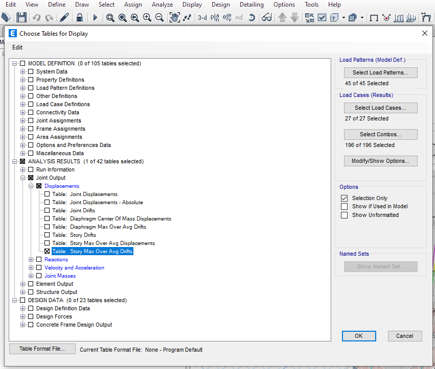

The Story Max Over Avg Drifts Table below shows the Drift Ratio as highlighted on the tables. The amplification factor should be considered on the corresponding level whenever there is ratio exceeding 1.20.


Story Max Over Avg Drifts Table showing the Drift Ratio as highlighted at X-Direction
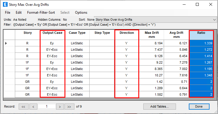

Story Max Over Avg Drifts Table showing the Drift Ratio as highlighted at Y-Direction
2. Calculation of Torsional Amplification Factor, Ax.
After confirming the presence of a torsional irregularity, we will then calculate the torsional amplification factor, Ax, using the equation provided by the ASCE 7-16 code, reference to equation 12.8.14 as per the below formula:

*Note that the above Ax, shall not be less than 1.0 and its not required to exceed by 3.0
where:
δmax: Maximun displacement values taken from ETABS Analysis results.
δavg: Average displacement values taken fro ETABS Analysis results.
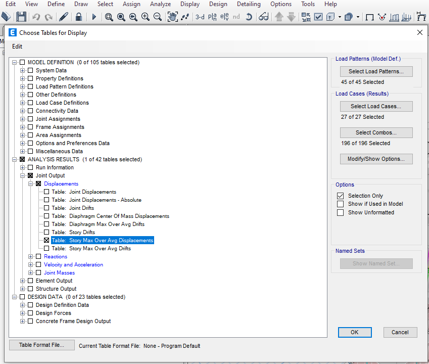
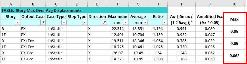
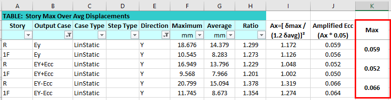
To know the maximum and average displacements values , we extract the Story Max over Avg Displacements Table in our ETABS Model by going to View > Display Table>Analysis Results>Joint Output>Displacements>Story Max over Avg Displacements.

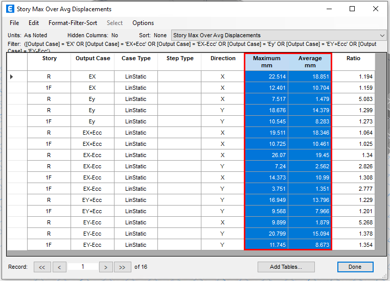

Maximum and Average Displacement Table
Extract the above table to Excel to calculate the Ax in each floor level and Amplified Eccentricity as follows:
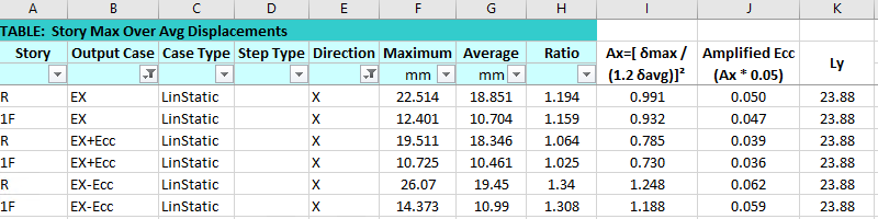

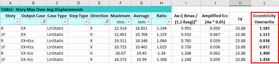
Table 2.1
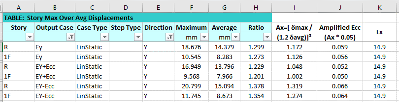

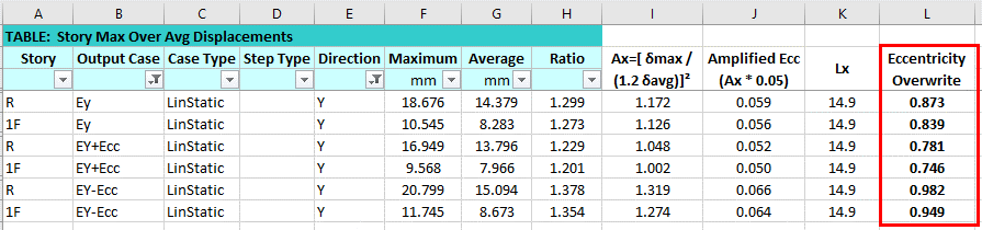
Table 2.2
3. Amplify the Accidental Torsion.
To amplify the eccentricity, the torsional amplification factor, Ax shall then be multiplied by the minimum eccentricity of 0.05 as shown on the column “J” of the above table 2.
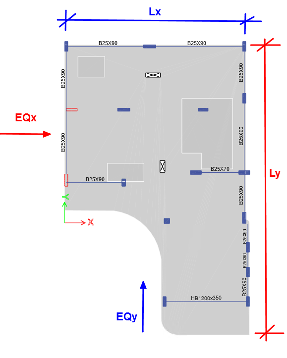
4. Eccentricity Length
The eccentricity length to consider is the perpendicular dimension to the direction of force in consideration. Let’s take a look at the screen shot below for your reference.

Two Methods on how to Apply the Effect of torsional irregularity in our model.
The ASCE7-16 code mandates a minimum eccentricity of 5%. Consequently, our building design necessitates addressing torsional irregularity as per code requirements, which entails amplifying these eccentricities to properly distribute forces. This involves overwriting the eccentricity values within our ETABS model. Below, we outline the two methods for accomplishing this task:
Method 1:
Calculate the new eccentricity values by multiplying the eccentricity length with the amplified eccentricity factor. The resulting values are depicted in the tables below.


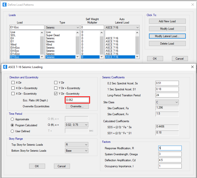
The new eccentricity values will be use to overwrite the eccentricities on our model. Proceed with unlocking the model and go to Define>Load Pattern following the screenshot below:
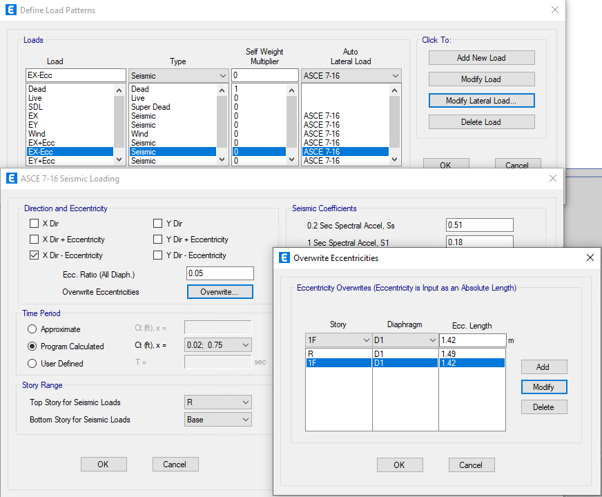

Do the same in all seismic load patterns where the ratio of drifts exceeds 1.20 according to the very first drift check.
Method 2:
Perhaps method two is not that tedious compared to method 1, since we have to calculate only the maximum amplified eccentricity in each level corresponding to seismic load patter. We don’t need the eccentricity length to define them. The resulting values are depicted in the tables below.


The maximum eccentricity values will be use to overwrite the eccentricities on our model. Proceed with unlocking the model and go to Define>Load Pattern, following the screenshot below:

Do the same in all seismic load patterns where the ratio of drifts exceeds 1.20 according to the very first drift check.
Why It’s Important to do the above exercise?
The seismic forces exert a significant influence on our structure, particularly impacting the vertical elements such as shear walls and columns. It’s widely understood that these vertical elements serve as the backbone of our structure. Hence, any inaccurate design could compromise the strength and stability of our entire structure that may lead to structural failure and collapse.
What do you think about this article? Let us know your thoughts and comment down below. You can also follow, like, and subscribe to our social media pages below to be updated with the latest posts.

![]()