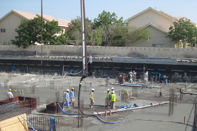
A raft foundation or mat footing is a reinforced concrete foundation system that supports multiple columns and/or structural walls over a large continuous area. It is commonly adopted where column loads are relatively high, individual footings would occupy a significant portion of the available area, or the soil has relatively low bearing capacity. Because the raft interacts directly with the supporting soil, its design requires both structural and geotechnical verification.
Following the completion of the raft foundation design, a systematic post-design or model review should be carried out to confirm that the adopted geometry, soil pressures, uplift resistance, settlement, punching shear capacity, and reinforcement are adequate. This post-design check is particularly important when the raft has been designed using finite-element software such as SAFE, as the software results must be reviewed against the design assumptions, project requirements, and applicable design codes.
Here are the important design checklists of Raft Foundation design that you should aware of:
1. Geometry/SAFE Modeling
The first post-design check is to verify the geometry of the raft foundation against the latest approved architectural, structural, and geotechnical information.
The overall raft length, width, thickness, levels, steps, drops, openings, and thickened portions should be reviewed. The raft perimeter should also be checked against the approved foundation layout to ensure that the structural analysis model accurately represents the actual construction geometry.
Particular attention should be given to the location and dimensions of columns and structural walls. The column and wall locations in the analytical model must correspond with the latest structural plans. Any transfer columns, floating columns, heavily loaded walls, or concentrated loads should be specifically identified because they may govern punching shear and local flexural design.
The raft thickness should be reviewed against the required structural capacity, particularly punching shear and one-way shear. Where different thicknesses or drop panels are provided, the changes in thickness should be correctly incorporated into the analysis model.
The following should take in consideration when checking the geometry/model of RAFT foundation:
- Overall raft dimensions
- Raft thickness and levels
- Column and wall locations
- Drop panels and thickened regions
- Openings and penetrations
- Raft edges and projections
- Concrete cover
- Foundation depth and founding level
Any discrepancy between the design model and construction drawings should be resolved before finalizing the reinforcement design.
2. Punching Shear Check
Punching shear is one of the most critical structural checks for a raft foundation. Concentrated column or wall reactions can produce high two-way shear stresses around the loaded area.
The punching shear capacity should be checked around all critical columns and concentrated loads, including interior, edge, and corner columns where applicable. Columns carrying high axial loads or significant moments should receive particular attention.
The design punching shear demand should be compared with the available punching shear capacity in accordance with the applicable design code. In an ACI-based design, the critical perimeter is established around the loaded area and the design shear stress is evaluated considering the appropriate effective depth and material properties.
Where a column transfers significant bending moments to the raft, the effect of unbalanced moment transfer should also be considered because the moment can produce a non-uniform distribution of punching shear stress around the critical perimeter.
The post-design review should identify the governing punching shear location and confirm that the utilization ratio is acceptable. If the punching capacity is inadequate, possible design solutions include increasing raft thickness, providing a local thickening/drop, increasing column dimensions, or introducing appropriate shear reinforcement where permitted by the governing code.
When using SAFE software for example, a punching shear ratio less than 1.0 is genereally considred as adequate and safe in punching stress.
You can check the punching shear ratios in SAFE Model by navigating to DISPLAY>SHOW PUNCHING SHEAR DESIGN.
3. Soil Pressure-Minimum
The soil pressure-minimum in your SAFE Model should be reviewed to confirm that the raft remains adequately supported by the soil under the service envelope load combinations. This is to ensure that the pressure transmitted from the raft to the supporting soil does not exceed the allowable or design bearing capacity established by the geotechnical investigation.
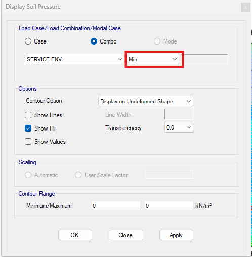
The following relationship provides the basic verification as far as SAFE Model is concern.
calculated soil pressure (min) ≤ Allowable/design soil bearing pressure
For a conventional raft designed assuming soil contact over the entire foundation area, excessive reduction in soil pressure or the development of tensile soil pressure may indicate partial loss of contact between the raft and soil.
The minimum soil pressure should therefore be checked under the relevant service and stability load combinations. The location of the minimum pressure should also be reviewed, particularly where substantial eccentricity or overturning moments are present.
If the analysis produces negative soil pressure, the result should not simply be accepted as a numerical output. The design assumptions must be reviewed to determine whether the soil is capable of resisting tension. In most conventional soil-foundation systems, tensile soil resistance is not relied upon.
Where significant areas of the raft become uplifted or lose contact, the foundation model may need to be revised using appropriate compression-only soil springs or other suitable soil-structure interaction assumptions.
4. Soil Pressure-Maximum
The soil pressure-max in SAFE Model is checked to ensure that the pressure transmitted from the raft to the supporting soil does not create tension stresses.
The soil pressure-max should be reviewed under service envelope load combinations, as applicable to the project’s geotechnical design criteria. The location of the soil pressure under tension stresses should be identified and fix to achieve a satisfactory design.
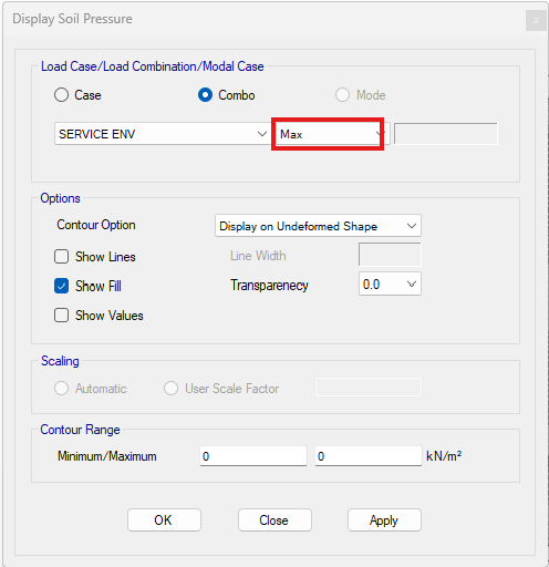
The check should be performed using the correct bearing capacity specified in the geotechnical report. Any reduction or increase in allowable bearing pressure due to foundation dimensions, embedment, groundwater conditions, or load duration should be considered where applicable.
Generally, for the raft to be safe from tensions stresses. A positive value of soil pressure registered in SAFE model should be ruled out. Example below is the tension stress registered in SAFE Model during the analysis of raft foundation. In this case this positive soil pressure has to be addressed to satisfy code requirement. Posible solution is adding weight by increasing the thickness of the raft.

5. Uplift Check
An uplift check is required where groundwater, hydrostatic pressure, buoyancy, or other upward forces may act beneath the raft.
The upward hydrostatic force should be determined based on the design groundwater level and the underside of the raft. The total stabilizing downward load should then be compared with the potential uplift force.
A suitable factor of safety or load combination should be adopted in accordance with the project geotechnical and structural design requirements. According to ASCE 7. The uplift due to water pressure can be verify against the below load cmbinations.
Uplift Load Combo 01: 0.90(DL+SDL)+H
Uplift Load Combo 02: 0.9DL+0.6SDL+H
where:
DL: Dead Load or serlfweight of structure
SDL: Superimposed Dead Load
H: Hydrostatic Loads
The uplift check should consider:
- Design groundwater level
- Hydrostatic pressure
- Raft self-weight
- Soil overburden, where applicable and permitted
- Permanent structural loads
- Temporary or variable loads where appropriate
- Waterproofing and drainage assumptions
The design should not rely on temporary loads or unreliable soil cover unless specifically permitted by the design criteria.
If the available resisting weight is insufficient, possible solutions include increasing raft thickness, increasing foundation depth, providing tension piles/anchors, or implementing an appropriate groundwater control and drainage system.
You can refer to out previous article on how uplift checks are being calculated and analyze.
6. Soil Settlement
Settlement is an important geotechnical consideration for raft foundations because excessive total or differential settlement can affect both the foundation and the superstructure.
The calculated settlement should be compared with the allowable settlement specified by the geotechnical report. Both total settlement and differential settlement should be considered. The allowable settlement for raft is usually 50mm, to be checked according to your soil investigation report.
The post-design review should verify that the soil parameters used in the structural model are consistent with the geotechnical investigation. Where soil springs or subgrade modulus values are used in SAFE, the adopted values should be checked against the geotechnical recommendations.
The settlement assessment should consider the distribution of structural loads. Areas beneath heavily loaded columns or walls may experience greater settlement than lightly loaded areas, potentially resulting in differential movement.
The following should therefore be reviewed:
- Total settlement
- Differential settlement
- Maximum settlement location
- Settlement between adjacent columns
- Soil stiffness/subgrade modulus
- Groundwater conditions
- Long-term consolidation where applicable
The calculated values should be reviewed by comparison with the allowable criteria established by the geotechnical engineer.
7. CrackWidth Check
When groundwater is present or the groundwater table is close to the underside of the raft foundation, a crack-width check should be performed to ensure adequate serviceability and durability of the reinforced concrete foundation. Groundwater can penetrate through cracks in the concrete, potentially causing water leakage, deterioration of the concrete, and corrosion of the reinforcement, particularly when aggressive chemicals or chlorides are present in the soil or groundwater.
The crack-width assessment should consider the serviceability load combinations, including the effects of sustained loads, bending moments, and restraint due to shrinkage and temperature changes. The calculated crack width should be compared with the allowable limit specified by the applicable design code and the project durability requirements. The acceptable limit may vary depending on the exposure conditions, groundwater aggressiveness, and whether the raft is required to provide a watertight barrier.
More of the crackwidth design can be found on our previous article. Please do check it out.
8. Reinforcement Check
The final stage is to verify that the reinforcement provided in the raft is adequate for the governing design actions.
The reinforcement should be checked in both principal directions and at both the top and bottom faces of the raft. The required reinforcement obtained from the analysis should be compared with the reinforcement shown on the structural drawings.
The following should be verified:
- Required versus provided reinforcement
- Top reinforcement in both directions
- Bottom reinforcement in both directions
- Minimum reinforcement
- Maximum reinforcement spacing
- Bar diameter
- Development length
- Anchorage
- Lap length
- Reinforcement continuity
- Additional reinforcement around columns
- Additional reinforcement around walls and openings
- Edge reinforcement
- Concrete cover
Particular attention should be given to areas over columns and walls, where top reinforcement may be critical due to negative bending, and areas between supports, where bottom reinforcement may govern due to positive bending.
The reinforcement shown on drawings should also be coordinated with the SAFE design strips and design assumptions. Reinforcement congestion around heavily loaded columns should be reviewed to ensure that the required bars can be practically installed while maintaining the specified concrete cover and spacing.
A raft foundation should not be considered fully designed simply because the structural analysis software reports acceptable design ratios. A comprehensive post-design check is required to confirm that the analytical model, foundation geometry, structural capacity, soil interaction, and reinforcement detailing are all consistent.
The principal post-design checks should include geometry, punching shear, soil pressures, uplift, soil settlement, crackwidth check and reinforcement. These checks provide a systematic means of identifying potential design deficiencies before construction.
Particular emphasis should be placed on punching shear around heavily loaded columns and walls, maximum soil pressure against the geotechnical bearing capacity, minimum soil pressure and potential loss of contact, uplift under groundwater conditions, settlement compatibility, and the adequacy and constructability of the final reinforcement.