The design of crane foundations is not an easy task as it involves safety risks that need to neutralize throughout the course of its service. In doing so, the designer should equip with technical know-how in order to produce a safe and sound design. Technical know-how involves at least the basic principle of how the design approach will be. Before we proceed, let us familiarize the parts of the crane that are mentioned in this article according to the figure below.
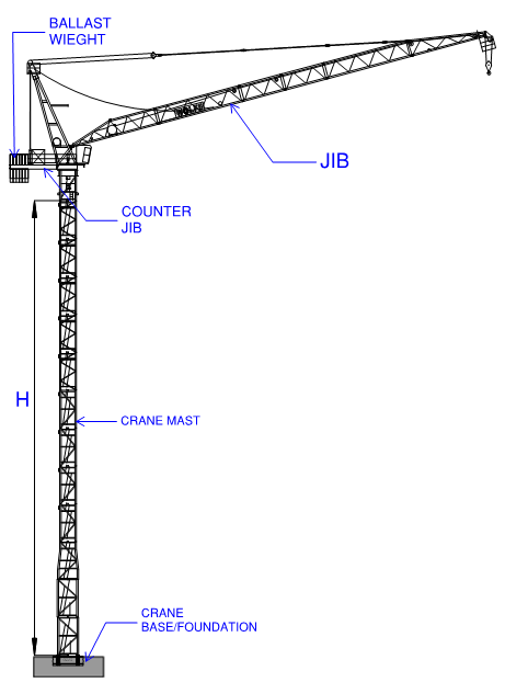
Figure 1.0: Basic Parts of the Crane (mentioned in this article).
Generally, crane mast legs can be mounted or cast on their foundations, and in some cases, it is fixed to the surface of the foundations in addition to concrete blocks known as ballast that use to counter the crane weight and its forces. Crane reactions differ and vary according to the model and the method of how the crane will be mounted to the foundation. Since cranes have reactions that differ according to the model, this article will discuss only the general approach to how the crane base is being designed.
1. Crane Model and Specifications
To start the design of crane foundations, the designer should gather all the necessary data needed in the design. The model name of the crane to be used in the construction and its technical data should be identified. Each crane model and its data differ from each other, so it is best to verify the model of the crane to use at the start. The crane’s technical data will give you the information needed in the design such as tower crane height (H), jib length, leg dimensions, spacing, and more importantly the foundation loads or reactions.
2. Crane Base Reactions
The reactions to consider in the design of the crane foundation are specified in the technical data as shown in Table 2.1. The maximum in-service or when the crane is operational and out-of-service or when the crane is at rest are used in the analysis. Crane reactions to the foundation include the twisting moment or the torque (Mt), design moment in X and Y directions (Mx and My), horizontal forces (Hx & Hy), and vertical (V) reactions. Note that the crane base reactions differ when the crane legs are embedded in the foundations or when using a ballast weight.
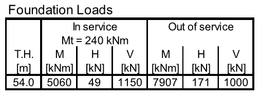 Table 2.1: Crane Reactions (Excerpt from Crane Data)
3. Load Cases Assignment
The crane base reactions specified in Table 2.1 should be considered in the calculations. Figure 3.1 shows the typical crane reaction schemes that are acting on the foundations. These reactions should apply in all possible locations or load cases when the crane is at rest and during the operations. The load cases in orthogonal and diagonal orientations as shown in Figure 3.2 should be applied in the calculations. The locations of the reactions should be rotated in all possible positions, though it is obvious that the critical is when the boom is positioned at 45 degrees. To distinguish the critical case, the load cases shall be checked by incorporating it via load combinations.
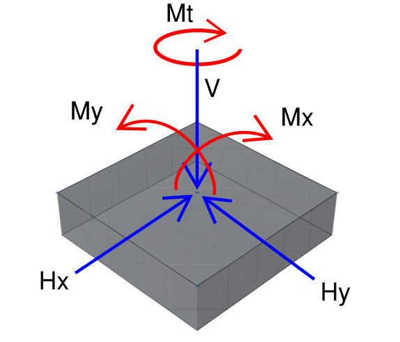
Figure 3.1 Schematic Crane Reactions in Foundations
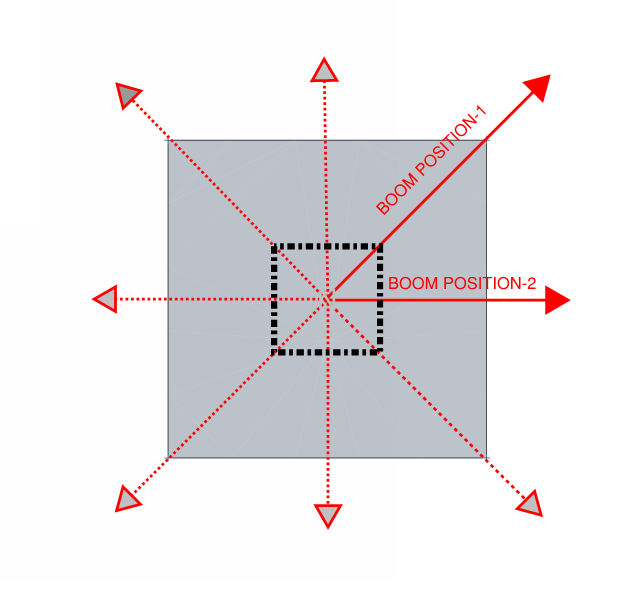 Figure 3.2 Crane Jib Positions Cases for In-Service and Out of Service Reactions
4. Load Combinations
To reflect the maximum and worst forces caused by the crane reactions, it should be incorporated in the load combinations specified by the code. The crane load cases shall be combined with the following basic load combinations. Only gravity loads are used in the combinations with the crane reactions. It is assumed that lateral loads (wind and seismic) will not occur at the same time during the crane operation.
4.1 Ultimate Limit State
-
-
-
- ULS 01 1.4 DL +1.4 SDL
- ULS 02 1.2 DL + 1.2 SDL +1.6LL
- ULS 03 0.9 DL + 0.9 SDL
- ULS 04 0.9 DL + 0.9 SDL + 1.6 H
-
-
4.2 Service Limit State
-
-
-
- SLS01 1.0 DL +1.0 SDL
- SLS 02 1.0 DL + 1.0 SDL +1.0LL
- SLS 03 1.0 DL + 1.0 SDL+1.0 H
-
-
5. Foundation Design
The crane foundation should be designed and assumed as a free-standing crane. This is to ensure that all the reactions and moments are being taken by the foundation itself. The designer can use any of the foundation types available. But the most common foundation to use is an isolated footing. A pile cap foundation is also applicable depending on the soil characteristic. In some cases, crane legs are cast along with the raft foundations or raft on piles. Regardless of which type of foundation to use, it should be designed and reviewed according to the following design checks.
5.1 Pull-out Check
For crane legs embedded into the foundation, the crane mast is anchored using four legs. Therefore a tension force will be developed and it is subjected to tensile loadings. In this regard, the said amount of tension force should be resisted through a concrete pull-out design. To prevent the tension and shear loading failures from happening, it should be designed according to the code set forth in Chapter 27 of ACI 318M-14 or Appendix D of ACI 318M-08. Additional ties should be provided in case of the concrete pullout is not sufficient.
5.2 Punching Shear Check
The compression force from the anchor developed caused by the vertical load should also be checked and designed according to punching as specified by the code. The thickness of the foundation should be sufficient enough to resist punching stress.
5.3 Crack Width Check.
When the foundation is subjected to hydrostatic pressure a crack width check is required. Although dewatering works are present, the designer should take into consideration the worst-case scenario when the dewatering works are no longer required. Crack width for the crane base slab can be assessed using service moments as per the procedure specified in ACI 224R. The crack widths in the X and Y directions of reinforcement are reviewed for the top and bottom surfaces of the foundation. The allowable crack width for the top and bottom of the foundations is 0.3mm as outlined in Section 1.3.
Practical Calculation Report Guide
A Practical Calculation Report Guide in Tower Crane Foundation Design embedded in a raft on piles is available in our E-Book Section for your reference. Grab yours! Refer to the image below!

What do you think about this article? Tell us your thoughts, and leave a message on the comment form below. Subscribe to our newsletter to be updated with the latest posts or follow us on our social media pages on the below icons.
[DISPLAY_ACURAX_ICONS]


Why no description of Wind Loads and its Combination have mentioned? Especially SLS combination 0.6 Dead + Wind?
As a designer, you can consider the wind loads according to your judgment. But usually, wind loads are not critical in this matter. That is why gravity loads have been emphasized in this article.
Hi,
I’m curious why there’s no seismic consider in load comb during crane service or rest condition? May the horizontal load provided by table 2.1 has included seismic or wind? Highly appreciated for your response.
Thank you.
This is because the seismic and wind forces are usually considered already by the crane manufacturers on the crane base’s in-service and out of service reactions data they provided.
I understand that ussually, the companies that fabricates cranes are multinational companies, and the wind forces may change from country to country, and if the country is in a hurricane prone area or not, and same happens with seismic loads change considerably from one country and area of a same country, I guess it should be specified explicit in the reactions the loads Criteria used to calculate the reactions.
someone what to share with me the report on tower crane foudation? I’m doing my master thesis on it.