


Hydrostatic uplift or the uplift pressure exerted by water in a structure having basements is a crucial thing to consider during construction. It may cause a project mishap if we don’t treat it well. As we all know, the water pressure can overturn the whole structure and cause a collapse during the early stages of construction. Don’t get me wrong, yes hydrostatic uplift should already consider in our design during the design and development stage and strength wise, an additional reinforcement already took care of it and that is fine. But the real question is does its weight or its mass is heavier enough to resist the upward force due to water pressure? How we are going to deal with it on the actual construction? Dewatering procedure may help to control the water away from our construction site, but we cannot keep the dewatering the whole life span of the construction as it is not an economical move. When is the best time to shut down the dewatering works? In this scenario, a hydrostatic check and calculations should be made by a Structural Engineer in charge to answer these questions.
ASCE 7-10, section 3.2.2 states that, in the design of basement floors and a slab below grade, the upward pressure of water shall be taken as the full hydrostatic pressure applied over the entire area. The hydrostatic load shall be measured from the underside of construction. Any upward loads shall be included in the design. How do we apply this clause in actual construction? When do we need to consider hydrostatic check or the uplift check in our design? Well if you still not aware, keep reading. This article will enlighten you on how to do a simple hydrostatic check calculation. Before we do, we should check some errands to make sure that there is really a need for hydrostatic checks.
Check for Groundwater Table
If our groundwater table is higher than the bottom of our foundation level, then a hydrostatic check is a must. In this way, we can easily imagine that our structure was submerged in water which means that the water pressure exists. The actual water table of the construction site is usually mentioned in the soil investigation report that every project should have.
How to Performed a Hydrostatic Uplift Check
To satisfy the code requirement, the mass of the sub-structure should greater than the load exerted by water applied to the entire area. In a simple equation or basic principle: Summation of downward load (due to the mass of the structure) per given area should greater than that of the vertical load (due to water) per given area. There is no specific factor of safety considered by the code, but it is safely said and we can conservatively assumed that the downward load should at least greater than 25% compared to the upward load due to hydrostatic load. You can also verify the factor of safety with the local authority which is ranging from 1.10 to 1.25 and adapt their requirement accordingly. For the sake of an argument, let us considered the 1.25 factor of safety in this example.
Uplift Check Equation
Mass of the structure over the uplift pressure ≥ 1.25; To apply safety factors, we can arrive on the following equation:

where:
-
- Ø: mass reduction factor, can be taken as 0.90
- W: the mass of the structure
- ω: specific weight of water
- h: height of water from the water table to the bottom of the foundation
- 1: Factor of safety
Example Problem:
Let us take a look at the basement below with the raft slab thickness of 2m, ground and first basement slab thick to be 0.35m and 0.4m respectively. The groundwater table was encountered at 5 meters below the natural grade line, use unit weight of concrete to be 25kN/m3:
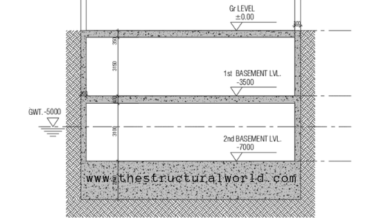
Basement Cross Section
Solution:
1. Calculate the Mass of the Structure, W (per meter height or thickness of the slab/raft) and conservatively neglect the weight due to retaining wall.
W= 25kN/m3( 0.35m + 0.40m + 2.0m) = 68.75 kN/m2
2. Calculate for Water Pressure
The pressure at a given depth acts equally in all directions. Therefore, the pressure due to water is directly proportional to both the depth and the specific weight of the water (ω) which is weight per unit volume: ω =ρg (N/mm3).
where:
-
- ρ= density of water (1000 kg/m3)
- g= gravitational acceleration (9.81m/s)
Due to Water Uplift:
ω = 9.81 kN/m3
h is the difference between the formation level and the groundwater table and can be calculated as:
h= [(7m+2m)-5m] = 4m
Using our Derived Equation:

; 0.90(68.75kN/m2 ) / 9.81kN/m3(4m+1m) = 1.26, hence oK!
In the event that it does not satisfy our equation, try to increase the mass of the structure by adding thickness on the slab or raft foundation until such time that it satisfies the equation. In the case of actual construction where the increase of thickness is not possible, consider the weight of the upper floors before shutting down the dewatering works.
What do you think about this article? Tell us your thoughts! Leave a comment on the section below. Subscribe to our newsletter to be updated with the latest posts or follow us on our social media pages on the below icons.

![]()


Surely the most critical stage is before the 1st basement level is cast?
Good information and straight forward analysis.
I have also considered the resistance to the hydrostatic force by using tension piles due to uneconomically expensive raft foundation thickness.
Thanks for the article. Very clear explanation.
In general, your blog is the best I have ever read. Please don’t stop posting topic.
Thanks Azhar!
Can you please mention any code which used 1 meter of water increasing as factor of safety
THe problem of bouyancy became an issue at my workplace a while back. Our department has used open bottom fiberglass manholes for years and the typical installation involved dewatering the excavation as required, placing the fiberglass manhole in the proper orientation for the sewer pipes, and pouring mass concrete around the base of the manhole, typically at least 1 foot thick and 1 foot wider than the manhole diameter all around. After an initial set, the excavation would be backfilled and compacted while the dewatering system remained operating. The interior base of the manhole would be finished with additional concrete, formed to provide a flow channel with built up concrete haunches to direct the flow. After construction was complete, the dewatering system would be removed and the ground water would return to seek its own level. Design was typically conservative with satuarated ground assumed up to finished grade. We had never had any problems with this construction, but the engineers managing the office one day decided that a 2-way reinforcing steel mat was required in the concrete base to resist “unopposed hydrostatic forces” that could cause the cured concrete to fail. I was assigned to determine what reinforcement was necessary. I stated that none was necessary as the weight of the manhole, concrete base, manhole lid and frame and the soil surcharge overcame the bouyant forces, the net force was downward and any resulting bending stress in the concrete was within the limits allowed by the ACI “plain” concrete building code. This resulted in much heated discussion and agravation. I finally told management that if they sincerely believed the reinforcement was necessary, they should just direct the crews to install the reinforcement and they wouldn’t get any arguments, however I believed it was not necessary. The bad feelings resulting from this situation eventually led me to find emplyment elsewhere, but to this day I wonder if their thoughts about “unopposed hydrostatic forces” had any meri
That’s interesting! They could have saved more If only they hear you out!
Excellent work….
Thanks!
Pingback: Method Statement for Dewatering Works | | The Structural World
The article was very useful
Thanks
thank you for the article.
i believe that this is ok for the short-term check using only the own weight of the structure during construction.
however, we can add the weight of super imposed dead loads for the Longterm check as per the codes.
note as well the factor of safety could be reduced if the check is considering the design ground water table which considers the future rise in water table.
Hi there
I think the problem is not to counter the uplift with concrete weight
its need deep investigation to know if the soil has tension stress or not
if we have tension pressure so we need nonlinear analysis to make tension stress zero and enlarge compressive stress if this analysis not work we need to with tension piles or give slabs and raft more thickness
Actually, check under tension stresses is a post-design checks to consider to make sure that there are no existence of positive tension stresses on our foundation.