
Your tasks for the analysis and design of the superstructure part of the building are over and you’re off for foundation design. You go through the geotechnical report and found out that the 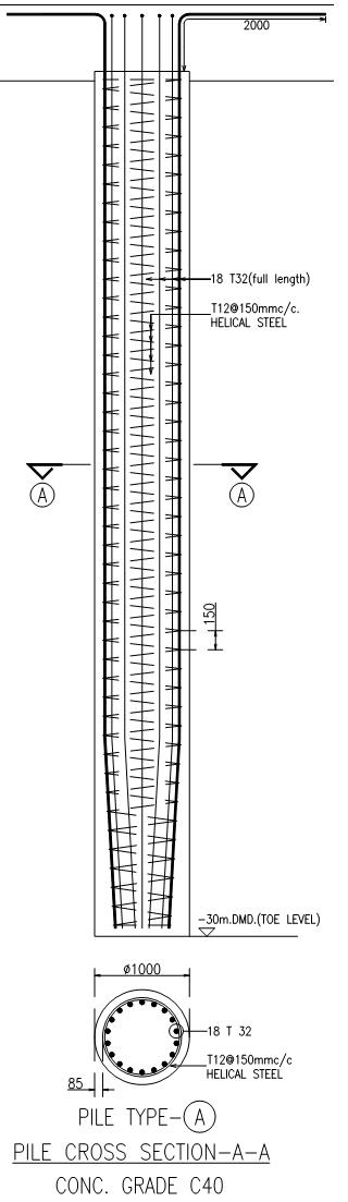 recommended foundation to use are either raft or pile foundation and notice that the soil bearing capacity is 50kN/m2. Since the geotechnical report recommends either of the two options in foundation design type, you’re confused, which is which? Suddenly, you remember that you are designing a high rise tower; there is no way a raft foundation may work here. This time you decided to go for a pile foundation.
Well, the above scenario in a structural design world is over exaggerated. In fact, choosing a foundation type on the building you are designing can be detected or should I say decided on the first stage of the structural design. It should be stated at first in the design criteria. Usually, the local official having jurisdiction can recommend what type of foundation is suitable depending on the soil type from where the project will rise.
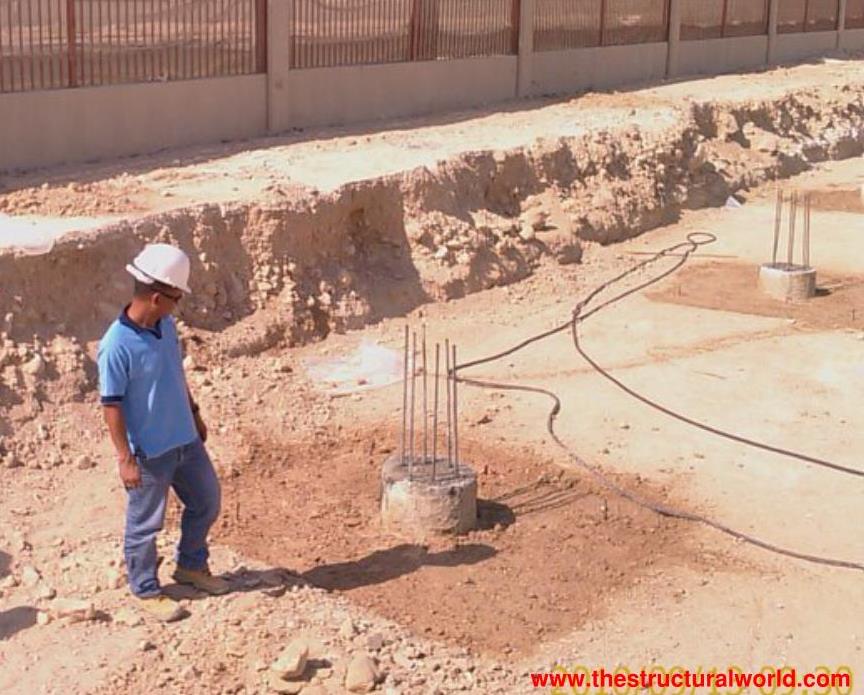
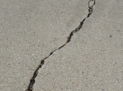
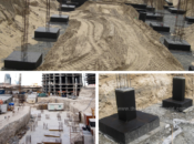
In this article, we will be discussing piles and their consideration in foundation design. We will start with a little definition of piles. Piles are used to transmit loads of the building to the hardest part of the soil strata. This is usually done in the areas where there is a very low soil bearing capacity and it comes with its duo, the pile caps. A typical detail of the pile can be seen in the image on the right, kindly click for a clearer view.
Design Considerations using Piles
We all know that piles or a group of piles are used to support a pile cap. For this to work, we have to provide a “support” for specified locations. This support can be interpreted as a “pin support”, but doing so will give as a very conservative result. Perhaps the best way is to use a spring constant (ks) or the so-called pile vertical stiffness as support. But how can we determine the spring constant? The spring constant (ks) is usually mentioned and derived in the geotechnical report, but if you are wondering, the pile spring constant or the pile vertical stiffness can be determined according to the recommended procedure set forth in EM 1110-2-2906 “Design of Pile Foundation”, Depth of the Army, US Army Corps of Engineers which is shown on the following formula:
Axial pile stiffness b33 = c33.AE/L
where:
- A=cross sectional area of the pile taken as πd^2/4
- L= Length of the pile
- E= Modulus Elasticity of the pile, usually taken as 4700
C33 is a constant that accounts for the interaction between the soil and the pile, evaluated as:
Δ/δ, by which Δ=PL/AE
where:
- P=Axial pile working load
- δ=the axial movement of the pile head due to axial load
Using the equations stated above, we can safely determine the vertical stiffness or the spring constant of any desired pile that we are going to use in foundation design.
How to incorporate the Spring Constant(ks) in Pile Cap Design
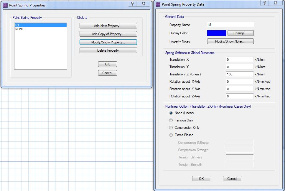
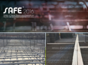
Since the pile cap is like a slab (but on the ground) we can use the SAFE program by CSI to design a pile cap. We just need to model this as a slab with its properties and incorporating the spring constant (ks) and assign the value of whatever is the result corresponding to the pile that we are going to use. Assign the vertical stiffness in translation Z calculated considering the equation above or as per the geotechnical report. Horizontal stiffness can be assigned in translation X and Y, if not given in the geotechnical report, it can be assigned as 10% of the vertical stiffness. The image below shows how to incorporate this in SAFE.
In SAFE, model the locations of piles as a null point, select the point in consideration and go to Assign>Support Data>Point Springs and the following dialogue box will appear.
The spreadsheets for the Design of PILE CAPS for two, three, and four piles are also available. Kindly select the images below for download!
| none |
|---|
| none |
Tell us your thoughts. Leave your message in the comment section below. Feel free to share this article, subscribe to our newsletter and follow us on our social media pages.
[DISPLAY_ACURAX_ICONS]
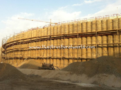

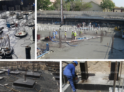
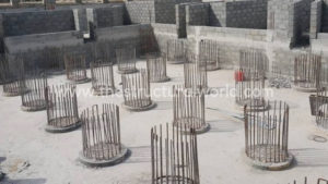
In the above photo, I would have no hesitation in rejecting the pile system for the following reasons;-
1. The piles show no excavation for tie beams between the piles at G.L. The purpose of the tie beams are to act in tension (restraint) in an earthquake. The design philosophy is to let the tie beams fail (if necessary, but hopefully not). for a small structure tie beams dimensions are 300 x 250 dependent on the water levels. Stirrups are close spaced 150 mm c/c and 2 D12 bars. For larger structures determine the lateral forces and drift for the E/Q according to Determinism, (not risk analysis) and that might be M.C.E (Maximum Credible Earthquake) or a special Geomorphological field and desk study. Do gather the latest research information as a result of the failure of soil, lateral spreading, liquefaction, soil structure interaction. Here at HNU on Bohol we teach the method of Professor Michael Pender as per the Geotechnical Society of New Zealand and SESOC.
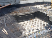
Thanks for a nice information Professor Paul, but I think the photo shows the piles on its cut off level only in preparation to pile cap above it.The level of the excavation on the photo is the bottom level of the pile cap and this pile cap will be connected by a foundation beam (tie beam) to another pile cap.There is no doubt a foundation beam (tie beam) is needed here to connect each pile cap for the reason stated in your comment above.
Knowing Mick, he would probably want a geotechnical engineer involved who has performed a suitable subsurface investigation and evaluated the subsurface conditions encountered along with the geohazards present for the site. Of course all of this has all been done and dusted long before we are discussing pile springs. I realize this is the structural portion presented here. I am glad HNU and hopefully all universities worldwide are teaching this to their students.
Nice and awesome writeup!
Please, how do I check punching of piles through pile caps in SAFE? Also, how do I check punching of supported column through pile caps in SAFE?
I won’t mind you sharing any reference materials with me via email.
Thanks
Thanks a lot Franklin, we are preparing a follow-up article regarding Pile cap design guidelines and that will include punching check considerations in SAFE or a manual check. In the meantime, kindly visit our site frequently or subscribe to our newsletter for any updates.
Many thanks for your response. I’d subscribe, but in the meantime kindly find a way to update me when you are done with the article.
Mr. Please help me, how to input “Rotation Stiffenes” in Spring Const SAFE.? Thanks
Thank you for the useful information.