


The Spandrel, Coupling or Link Beam as we often called it that connects the in-between walls when there is a wall opening due to door or elevator doors or as per the code defines refers to as a wall section in between the vertically aligned openings is sometimes taken for granted by the structural designer. Like any other structural member, the spandrel or coupling beam should also be designed and checked thoroughly by the structural designers. This is to ensure that flexural forces and shear forces developed more importantly on these coupling beams should be resisted accordingly.
The design of spandrel, coupling or link beams using ETABS can be summarized in the below procedure:
1. Assign Spandrel Labels in Coupling/Spandrel Walls.
Before proceeding with the spandrel labeling, make sure that the wall openings have been modeled accordingly. To model wall openings in ETABS refer to our youtube video for the tutorial. Once the wall openings have been set, run the model to proceed. In an already analyzed and run ETABS model, we begin with defining spandrel labels by going to Define> Spandrel Labels>Add New Name to setup names for spandrels. To assign the spandrel labels to the wall in considerations, select the spandrel wall above the elevator openings in case of a core/shear wall and assign the spandrel labels. For a detailed explanation of how to assign spandrel labels, visit our previous article, Pier and Spandrel Labeling for ETABS Shear Wall Design on how to assigned spandrel wall labels in ETABS.
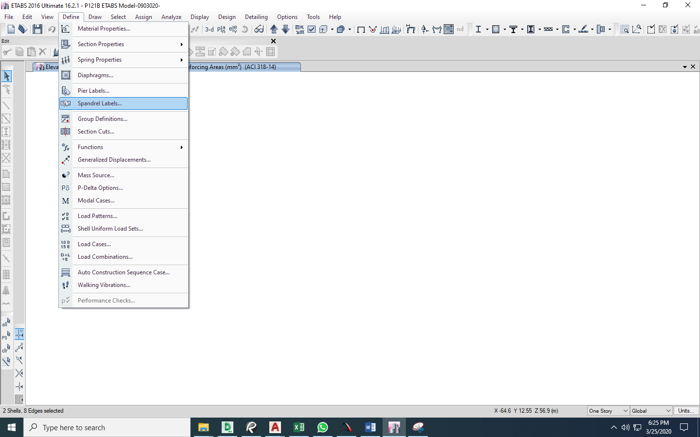
Figure 1.1 Define> Spandrel Labels
2. Design of Spandrel/Coupling Beam
Once all the spandrel labels have been set and assigned, select the spandrel beam that you want to design. Go to Design>Shear wall Design>Start/Design Check screenshot in Figure 2.1 below and ETABS will start the design check analysis. Be sure that the correct design combinations prior to this have been all set accordingly. You can review the design combinations used in the design by going to Design>Shear wall Design>Select Design Load Combinations as per Figure 2.2 below.
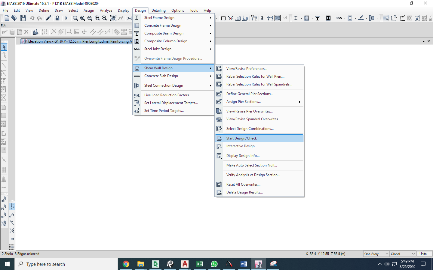
Figure 2.1 Design>Shear Wall Design>Start/Design Check
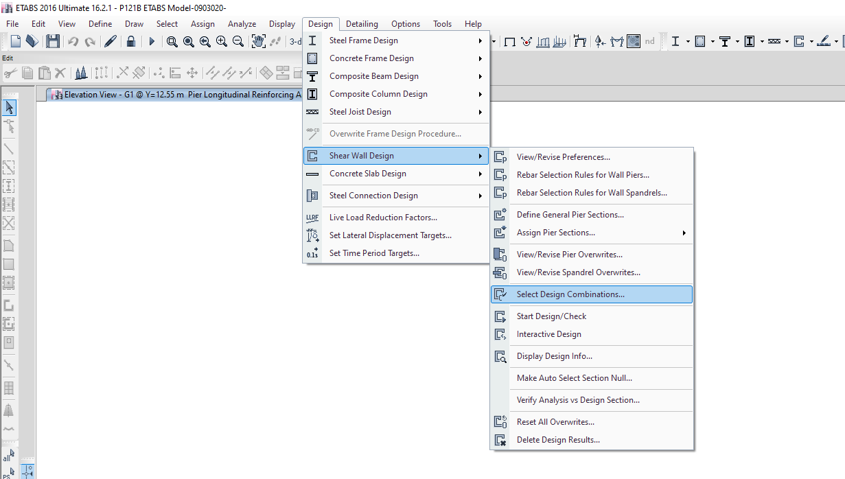
Figure 2.2 Design>Shear wall Design>Select Design Load Combinations
3. Interpreting the Design Results
The interpretation of ETABS design results in spandrel beams is then be performed after it finishes the design check analysis as mentioned in section 2. Select the spandrel beam in consideration once more or press the Get Previous Selection icon (Control + J) to select the previously selected spandrel beam. Once selected, go to Display>Show Table and tick the Shear Wall Spandrel Summary under the Design Tab screenshot in Figure 3.1 below and click Ok. The tabulated summary of the spandrel beams will appear. You can extract this table by right-clicking on the row of the table and click Export to Excel. A sample table according to Figure 3.2 below will be extracted. This table will give you detailed information on the area of reinforcements needed in the top and bottom of the spandrel beam. It will give you also the required shear reinforcement needed. In the event that error messages are shown, investigates the spandrel beam in the need of increasing the thickness of it.
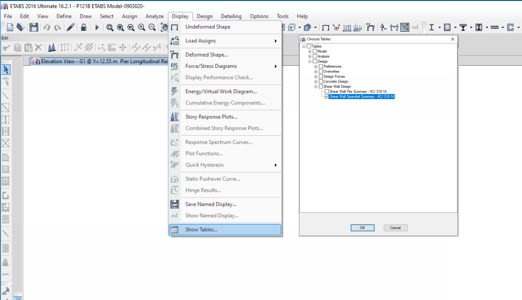
Figure 3.1 Display>Show Table>Shear Wall Spandrel Summary
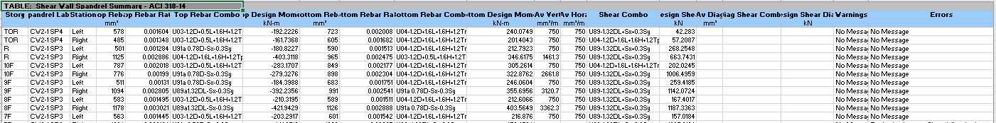
Figure 3.2 Extracted Shear Wall Spandrel Summary
4. Detailing of Reinforcements
The recommended typical reinforcement detail of the wall opening is shown in Figure 4.1 below. It is noticed that diagonal reinforcement should be placed as shown to beef up the strength of the spandrel/coupling beam and to be detailed in accordance with FigureR18.10.7 of ACI 318-14. However, the number of the top and bottom rebars and the spacing of stirrups/link reinforcement varies according to the ETABS output results as per the top rebar, bottom rebar and shear bars (Av) respectively as analyzed and as referred to Figure 3.2 above.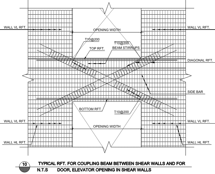
Figure 4.1 Typical Reinforcements for Coupling/Spandrel Beam Between Shear Walls and for Door and Elevator Openings
What do you think about this article? We love to hear from you! Leave a message in a comment section below. You can also follow, like and subscribe to our social media pages below to be updated with the latest posts.

![]()


Nice article