
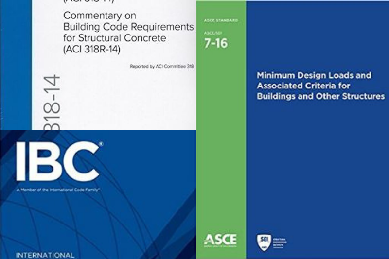
As mentioned in the previous article, Seismic Analysis: UBC 97 provisions, the seismic analysis in the design of buildings especially high rise towers is a very important factor to consider. Because earthquake loads together with the wind loads have a huge impact on the design result. In fact, most of the building design results were govern with the seismic loads. Calculating the seismic forces can be determined using the seismic parameters specified by the code. These parameters can be found on the seismic design codes available such as ASCE 7, IBC and UBC-97. Although these codes are recommended code to use in seismic, the use of these codes is still depending on the local authorities from where the project is located.
This article is a comparison with the previous article Seismic Analysis: UBC 97 provisions, we will tackle the Seismic Analysis provisions as specified in ASCE-7 and IBC. We will summarize the different seismic parameters that we often use in the Seismic Analysis according to ASCE and IBC. These parameters are specified below; most of the images here are an excerpt from the ASCE-7 and IBC-12.
Risk Category and Seismic Importance Factor
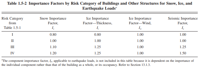
The first thing to consider is to identify the risk category and seismic importance factor of the project according to the nature of occupancy. We can base the risk category on Section 1604.5 of the International Building Code (IBC) 2012, Table 1604.5 “Risk Category of Buildings and Other Structures”. We can easily identify the risk category of the said table according to the Table 1604.5 below. And from the risk category identified in Table 1604.5, the seismic importance factor, Ie, can be found in Table 1.5-2 of ASCE 7-10 below.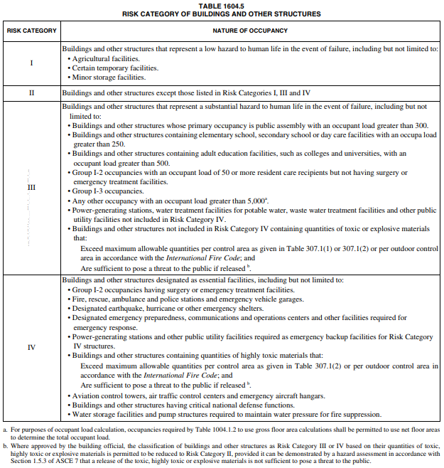
Site Coefficients
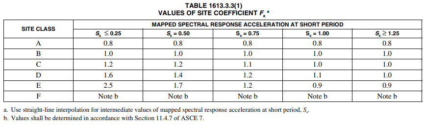
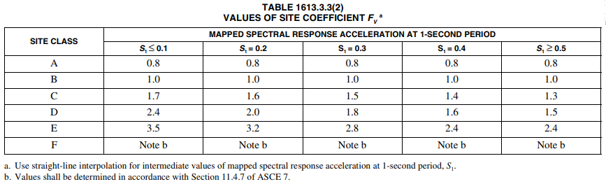
A site coefficient, Fa, and Fv should be defined as well. The site coefficients, Fa and Fv, can be found from Tables 1613.3.3(1) and 1613.3.3(2) of the International Building Code (IBC) 2012 respectively. Table 1613.3.3(1) requires knowing the site class of the structural building location and the mapped spectral response acceleration at short periods, SS. Table 1613.3.3(2) requires knowing the site class of the structural building location and the mapped spectral response acceleration at the 1-second period, S1.
Determination of SMS, SM1, SDS, SD1
SMS is the mapped maximum considered earthquake spectral response acceleration for short periods adjusted for site class effect. It can be determined according to Equation 16-37 of the International Building Code (IBC) 2012, which is equal to the site coefficient, Fa, multiplied by the mapped maximum considered earthquake spectral response acceleration for short periods, SS.
SM1 is the mapped maximum considered earthquake spectral response acceleration for 1-second period adjusted for site class effect. According to Equation 16-38 of the International Building Code (IBC) 2012, it is equal to the site coefficient, Fv, multiplied by the mapped maximum considered earthquake spectral response acceleration for the 1-second period, S1.
SDS is the design spectral response acceleration coefficient for short period. It can be calculated according to Equation 16-39 of the International Building Code (IBC) 2012, which is equal to two-thirds multiplied by the mapped maximum considered earthquake spectral response acceleration for short periods adjusted for site class effect, SMS.
SD1 is the design spectral response acceleration coefficient for the 1-second period. Equation 16-40 of the International Building Code (IBC) 2012 tells us that it is equal to two-thirds multiplied by the mapped maximum considered earthquake spectral response acceleration for the 1-second period adjusted for site class effect, SM1
Seismic Design Category, SDC
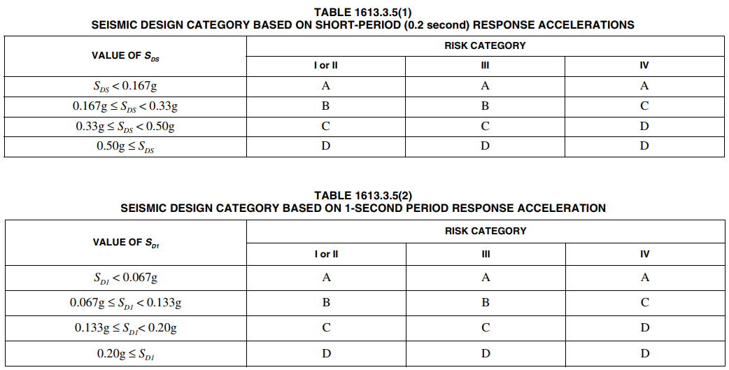
To determine the appropriate seismic design category refer to Tables 1613.3.5.(1) and 1613.3.5.(2) of the International Building Code (IBC) 2012 as per the figures below.
Response Modification Factor, R
Response modification factor, R, is also required and can be determine using figure Table 12.2-1 of ASCE 7-10 below.

Elastic Fundamental Period, Ta
To determine the elastic fundamental period of the building, use the Equation 12.8-7 of ASCE 7-10 can be simplified as follow.
Seismic Response Coefficient, Cs
The seismic response coefficient, Cs, is based on Equation 12.8-2 of ASCE 7-10. The seismic response coefficient is equal to design spectral response acceleration coefficient for short period, SDS, times the seismic importance factor, Ie, divided by the response modification factor, R.
Effective Seismic Weight
The effective seismic weight of the structural building should also be calculated. This is equal to the number of building stories multiplied by the weight of each building story.
Calculation of Seismic Base Shear
The base shear, V. can be calculated as per the Equation 12.8-1 of ASCE 7-10, which is equal to the seismic response coefficient times the effective seismic weight.
Find Distribution Exponent, k
Finding the distribution exponent, k according to Section 12.8.3 of ASCE 7-10, the distribution exponent is equal to 1.0 for buildings with an elastic fundamental period less than or equal to 0.5 seconds and is equal to 2.0 for buildings with an elastic fundamental period greater than or equal to 2.5 seconds. For structures having an elastic fundamental period between 0.5 seconds and 2.5 seconds, we will use linear interpolation to find the distribution exponent.
We need also to calculate a parameter for each building story equal to the weight of each story multiplied by the height from the base to the story to the power of the distribution exponent.
Vertical Distribution Factor, CVX
The vertical distribution factor, Cvx, is equal to the percentage of base shear that is assigned to each floor level. The formula for base shear is given in Equation 12.8-12 of ASCE 7-10 below.
Determine Seismic Lateral Force for Each Level, FX
According to Equation 12.8-11 of ASCE 7-10, the lateral force at each level of the building is equal to the vertical distribution factor for each level multiplied by the seismic base shear which can be simplified as:
Seismic Story Shear, VX
The seismic story shear, Vx, is according to Equation 12.8-13 of ASCE 7-10.
Overturning Moment, MX
Overturning Moment is also required to be calculated.
Find Deflection Amplification Factor, Cd
The amplification factor, Cd, is according to Table 12.2-1 of ASCE 7-10 below.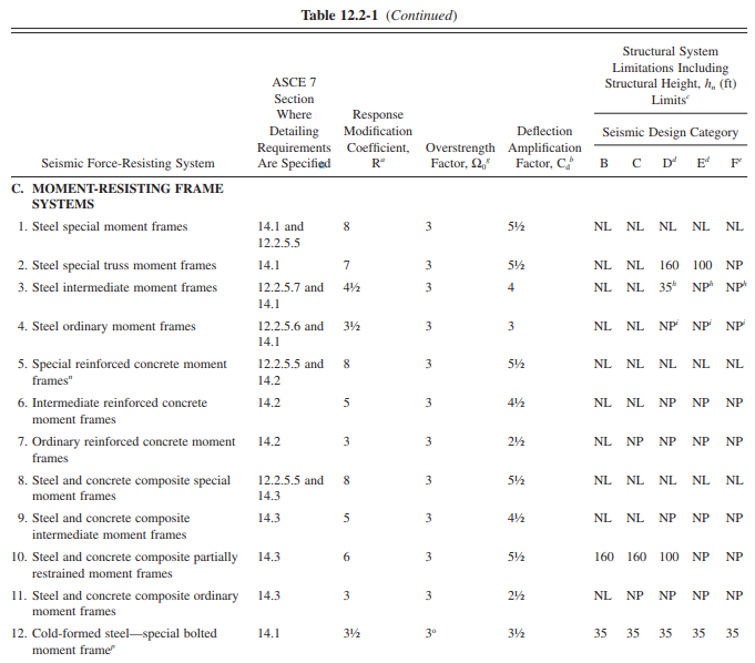
Lateral Deflection at Each Level
Based on Equation 12.8-15 of ASCE 7-10, it is equal to the deflection amplification factor times the elastic lateral deflection at each level under seismic lateral forces divided by the seismic importance factor.
Stability Coefficient
Evaluate the stability coefficient for each level per Equation 12.8-16 of ASCE 7-10. It is equal to the total un-factored vertical design load at and above each level times the design story shift times the seismic importance factor divided by the product of design story shear, story height below the level in consideration, and deflection amplitude factor. The maximum value for stability coefficient is found using Equation 12.8-17 of ASCE 7-10. According to Section 12.8.7 of ASCE 7-10, if the stability coefficient is less than 0.1 for all floor levels, then P-delta effects don’t have to be considered.
Further calculation checks should be performed on the following accordingly:
- Design Story Drift: Calculate the design story drift which is equal to the difference in deflections of the centers of mass of any two adjacent stories.
- Un-factored vertical design load, Px: The total un-factored vertical design load at and above each level should be calculated.
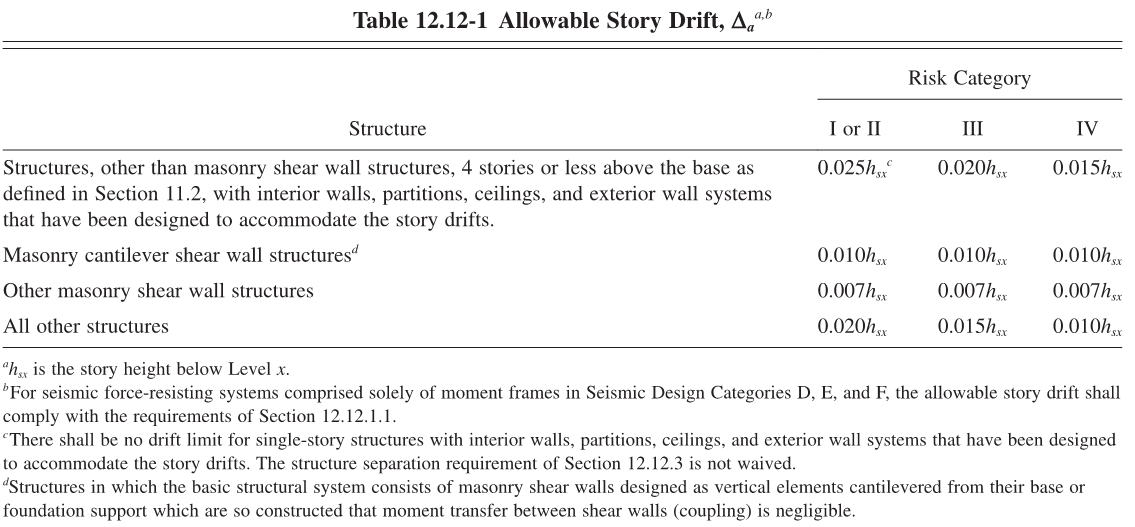
- Check Design Story Drift: The allowable story drift can be found from Table 12.12-1 of ASCE 7-10 as shown on the figure below. The allowable story drift should be greater than or equal to the design story drifts for each floor level.
The author strongly suggests to have you a full copy of ASCE-7 and IBC 2012 design codes when doing a seismic analysis. The above are guidelines only for the reader to easily locate the parameters needed in the seismic analysis using ASCE and IBC codes.
What do you think of the above this article? Tell us your thoughts! Leave your message in the comment section below. Feel free to share this article, subscribe to our newsletter and follow us on our social media pages.
![]()
 Copyright secured by Digiprove © 2018-2019 The Structural World


I want to design building with IBC 2012 ASCE 7-10.So please give me pdf paper so that i can download it.
I am working on a hospital that has an importance factor of 1.5. Our jurisdiction has adopted IBC 2021. The HVAC equipment provider has submitted equipment that bears the OSHPD/IBC2012 Certification.
How can I compare the requirements of the 2012 certification vs. those included in the 2021?