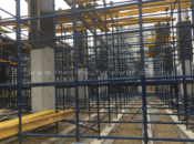


We all know that columns are the vertical members of a building structure that use to support the slabs and beams. It serves as a backbone of the structures so we can achieve the height that we wanted in a given project. A column comes with different types that vary in shapes and sizes depending on the loads and conditions of a structure. Design of columns had a different approach according to each type, whether it is a plain concrete column, a reinforced concrete column, a steel column and a composite one. Although the design differs accordingly, columns are classified and designed according to its length, the short and the long column.
Generally, short columns are columns that can be designed according to the load it can carry without considering its length. But, if the length of column maybe increases than usual, chances are it may fail in lateral buckling and can be designed as slender or long columns.
In this article, we will dig in the ACI 318-14 for the design criteria for columns and its considerations. Let’s begin.
Design Considerations for Columns
The design of the column can be done initially by determining the area of the vertical reinforcements it occupied in a given area of concrete. According to the ACI code, the area of vertical reinforcement of columns ranges from 1% to 8% of the column’s gross area (Ag)
Vertical Reinforcement = 0.01Ag to 0.08Ag ACI 318-14, Section 10.6.1.2)
Columns subjected to Axial Strength and Flexural Strength
If the column is subjected for axial load only, although pure axial load without moment is not a practical case for a column, the nominal axial compressive strength Pn, shall not exceed Pn, max according to section 22.4.2.1 and summarizes as follows:
Condition:
Pn,max = 0.80Po for tied column
Pn,max = 0.85Po for spiral column

Note that the factor 0.80 and 0.85 multiplied to Po is used to actually counter the effect of any eccentricity and Po shall be calculated by:
Po=0.85fc’(Ag-Ast) + fyAst (ACI 318-14, Section 22.4.2.2)
Where:
- Ast: total area of vertical reinforcement
- Ag: gross area of a column
- fc’: compressive strength of concrete
- fy: yield strength of rebar
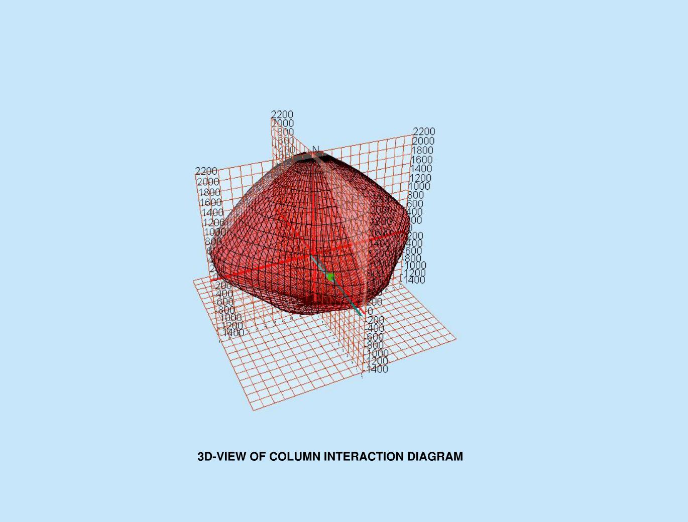
Columns subjected to Axial Strength and Bending
When the column is subjected to primary moments caused by applied loads or joint rotations, the axis of the columns deflects laterally. This deflection causes additional moments applied to the columns which are equal to the column load multiplied by the deflection. This moment is called the secondary moment or also known as the P-delta effect. The design of these columns can be determined and design by the following:
Check for Slenderness
Slenderness effect shall be permitted to be neglected if it satisfies the following (6.2.5):
For Columns not braced against sideways
klu/r ≤ 22
For columns braced against sideways
klu/r ≤ 34+12 (M1/M2) and klu/r ≤ 40
where:
M1/M2 is negative if the column is bent in single curvature and positive for double curvature.
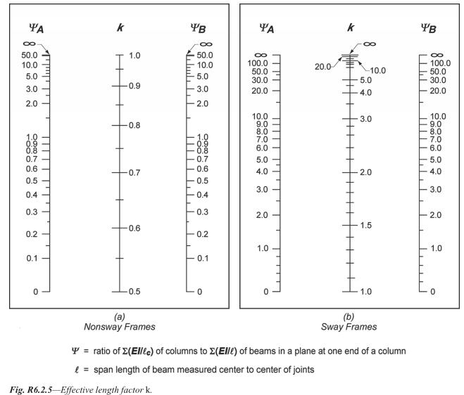
the radius of gyration, r shall be calculated by 0.3 times the dimension of stability being considered for rectangular columns, 0.25 for circular columns or the formula below:

Effective length factor,k shall be determined by Figure R.6.2.5 below as excerpts from ACI 318-14.
Slenderness Effects and Moment Magnification Method (6.6.4.5)
If the slenderness in a column is being permitted, then a Moment magnification is required in accordance with the following:
For a non-sway frame, the factored moment used for the design of columns, Mc shall be the first factored moment, M2

Magnification factor


if it exceeds

For sway frames, the Moment Magnification M1 and M2 shall be calculated as:


If
where:


Tell us about your thoughts! feel free to leave your comment below.
![]()